R500
April 2017
Series 8 C300 Controller User's Guide
Honeywell
187
7. C300 Controller Operation
7.4. Control Builder block icon descriptions
7.4
Control Builder block icon descriptions
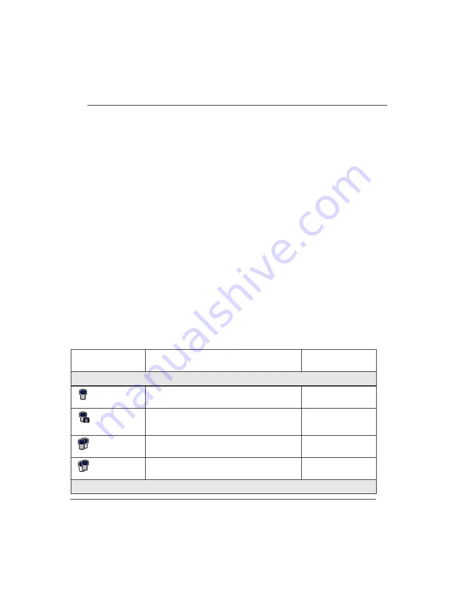
Adding a C300 Controller block (non-redundant or redundant) to the Control Builder
Project tab, results in the appearance of an icon that represents a single C300 Controller
or redundant controller pair. Once the C300 Controller block has been loaded, the C300
Controller icon appears in the Monitoring tab. The appearance of the icon in the
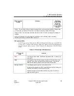
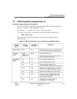
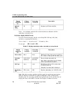
Monitoring tab is determined by the C300 ICONSTATE parameter which is derived
from these C300 Controller parameters:
Execution State parameter (C300STATE)
Redundancy Role parameter (RDNROLESTATE)
Redundancy Synchronization State parameter (RDNSYNCSTATE)
Soft Failure parameter (SOFTFAIL)
When a single C300 Controller is defined, the icon appears as a single controller icon.
When a redundant C300 Controller is defined, two icons appear, one representing the
primary controller on the left and the icon representing the secondary controller on the
right. The appearance of either icon on top in a redundant controller pair indicates the
active controller.
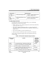
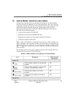
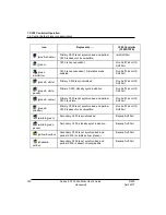
The following table shows the various appearances that the C300 Controller block icon
assumes based on the current C300 state and status.
Table 12 C300 Controller icon indications in Control Builder
Icon
Represents . . .
C300 Controller
(C300STATE)
Project Tab
(gray)
C300 Controller configured for non-redundant
operation.
N/A
(gray,
simulation)
C300 Controller configured for non-redundant
operation. Simulation mode enabled.
N/A
(gray & white)
C300 Primary configured for redundant
operation.
N/A
(white & gray)
C300 Secondary configured for redundant
operation.
N/A
Monitor Tab


