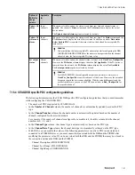
• The DSB communicates with the slave devices through this address. The slave device address must be
unique for a Protocol Block.
Attention
•
For GENPADSB, the transparent segment coupler displays all devices connected to the PROFIBUS PA
network as if they were PROFIBUS DP field devices.
•
For GENPAGWDSB, the PROFIBUS DP/PA link, Siemens DP/PA link IM-157, is a DP slave that acts as a
proxy for the PA field devices. The DP/PA Link reserves one PROFIBUS DP slave address.
11
In the
Device Type
box, type the description of the device type.
12
In the
Connection Break TimeOut (Sec)
box, type the duration in seconds during which the network
communication break needs to be filtered off.
If the communication break condition persists even after this time, then the status of the slave device is set to
“
Communication Error
.” This parameter is applicable only when the slave device is disconnected from the
Profibus network. If the complete Profibus network is down, the status of all slave devices is set to
“
Communication Error
” immediately.
13
Select the
Connection Break Timeout applicable for Network Down
check box if you want the output
channels to initialize back from the user-defined values after the connection break timeout timer is exceeded.
If the complete Profibus network is down and you have not selected this check box, the status of all slave
devices is set to “
Communication Error
” immediately.
However, if you have selected this check box and the complete Profibus network is down, the status of all
slave devices are set to “
Communication Error
” after the connection break timeout is exceeded.
14
Select the
Reset counters
check box if you want to reset all static counters.
15
Click the
Slave Status
tab.
Attention
The
Slave Status
tab displays the slave communication standard status bits and extended diagnostic information in
the Monitoring view. .
16
Click the
Alarms
tab.
The
Alarms
tab is only applicable to the Generic DSBs and the DRIVEDSB as you can configure alarms
only for these DSBs.
17
Click the
PDC
tab.
Attention
The
PDC
tab of the DSB block is used for defining the PDCs. You cannot proceed with the DSB configuration
until you complete the PDC configuration. To configure the PDCs, see section Configuring the PDC tab.
18
Use the online help as a guide to complete the configuration entries on all other tabs.
19
Click
OK
.
7 DEVICE SUPPORT BLOCK (DSB)
149
Summary of Contents for Experion PKS
Page 1: ...Experion PKS PROFIBUS Gateway Module User s Guide EPDOC XX88 en 431E June 2018 Release 431 ...
Page 8: ...CONTENTS 8 www honeywell com ...
Page 10: ...1 ABOUT THIS GUIDE 10 www honeywell com ...
Page 32: ...4 PROFIBUS GATEWAY MODULE PGM INSTALLATION 32 www honeywell com ...
Page 58: ...5 PROFIBUS GATEWAY MODULE PGM BLOCK 58 www honeywell com ...
Page 69: ...6 PROTOCOL BLOCK 69 ...
Page 103: ...5 Click OK 6 PROTOCOL BLOCK 103 ...
Page 110: ...6 PROTOCOL BLOCK 110 www honeywell com ...
Page 183: ...PDC Details tab Figure 6 Detail Display of PDC Details tab 7 DEVICE SUPPORT BLOCK DSB 183 ...
Page 186: ...7 DEVICE SUPPORT BLOCK DSB 186 www honeywell com ...
Page 231: ...9 PROFIBUS I O MODULE PIOMB FUNCTION BLOCK 231 ...
Page 232: ...9 PROFIBUS I O MODULE PIOMB FUNCTION BLOCK 232 www honeywell com ...
Page 236: ...10 PROFIBUS GATEWAY MODULE PGM CONFIGURATION EXAMPLE 236 www honeywell com ...
Page 264: ...13 PROFIBUS GATEWAY MODULE PGM TROUBLESHOOTING 264 www honeywell com ...


