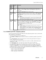
• You must select the appropriate PPO type PDC from the
PDC type of the Drive DSB
column.
– To access drive parameters through the PKW PDCs, you must configure both an input and an output
PKW PDC, irrespective of whether you have channels configured for both. If you configure only one
PKW PDC, an error is reported while loading the Drive DSB.
– You can have a maximum of one "PKW inputs" PDC and one "PKW outputs" PDC, since there can be
only one net tag that maps to that 8-byte area. The DSB needs both an input and an output PKW PDC to
write to the PKW request (the PKW In 8 bytes) and to read the PKW response (the PKW Out 8 bytes)
respectively. Therefore, without an input and output PKW PDC, the DSB cannot perform the PKW
processing.
– The PKW PDC performs a size check at runtime to verify that the data area is exactly 8 bytes. If the
module data size for a PKW PDC is not 8 bytes, that PDC state (PDCSTATE) changes to "Configuration
Failed" . You can recover this state by re-configuring the PDC to point to the correct net tag (which is the
8 byte PKW area) and reloading the DSB.
– Even though the PKW PDCs can have 32 channels, all the 32 channels do not use 8 bytes
simultaneously. Instead, each channel "takes a turn" for using the 8 bytes for its request/response
processing.
• The 16 DI/DO channels of the first input/output PPO type PDC are pre-populated by the status/control word
bit meaning/description depending on the drive's control mode.
• You cannot change the channel type for the first 17 channels in an input or an output PPO type PDC.
However, you can change the channel type for the configurable channels.
• In the
Channel Number
column, the channel number is automatically updated based on the number of
channels configured for the selected module.
For example, if the number of channels configured for a module is 4, then this column lists the channel
numbers as 0, 1, 2, and 3.
• The
Channel Data Offset
column displays the data offset of the channel in bytes starting at the location
defined by the net tag.
For example, the location defined for the PDC standard channels of DI and DO of PPO type 3 and 4 have
the data offset of 0. The location defined for the PDC standard channels of DI and DO of PPO type 1, 2 and
5 have the data offset of 8.
• The data offsets are automatically set when you select a specific PPO type. For additional channels that do
not use the PKW area, you must configure the data and bit offset appropriately.
• For PKW PDC types, the
Channel Data Offset
column is disabled.
• The
Bit Offset
column displays the offset of the channel in bits starting at the location defined by the data
offset.
• For PKW PDC types, the
Bit Offset
column is disabled.
• In the
Low Range
column, you must define the low range of the channel data in the FLOAT32 format.
• In the
High Range
column, you must define the low range of the channel data in the FLOAT32 format.
• To create channels mapped to the PKW area for acyclic data exchange, you must select the section type in
the
PKW Section Type
column.
• To configure the PKW area for the acyclic data transfer, you must enter a valid parameter number in the
Parameter Number
column.
You can type multiple parameter numbers for the same PKW area.
• To read or write a value, you must select the parameter sub-index in the
Array Parameter sub-index
column.
This column is available for configuration only if you select the
Section Type
as
PKW Array
.
7 DEVICE SUPPORT BLOCK (DSB)
159
Summary of Contents for Experion PKS
Page 1: ...Experion PKS PROFIBUS Gateway Module User s Guide EPDOC XX88 en 431E June 2018 Release 431 ...
Page 8: ...CONTENTS 8 www honeywell com ...
Page 10: ...1 ABOUT THIS GUIDE 10 www honeywell com ...
Page 32: ...4 PROFIBUS GATEWAY MODULE PGM INSTALLATION 32 www honeywell com ...
Page 58: ...5 PROFIBUS GATEWAY MODULE PGM BLOCK 58 www honeywell com ...
Page 69: ...6 PROTOCOL BLOCK 69 ...
Page 103: ...5 Click OK 6 PROTOCOL BLOCK 103 ...
Page 110: ...6 PROTOCOL BLOCK 110 www honeywell com ...
Page 183: ...PDC Details tab Figure 6 Detail Display of PDC Details tab 7 DEVICE SUPPORT BLOCK DSB 183 ...
Page 186: ...7 DEVICE SUPPORT BLOCK DSB 186 www honeywell com ...
Page 231: ...9 PROFIBUS I O MODULE PIOMB FUNCTION BLOCK 231 ...
Page 232: ...9 PROFIBUS I O MODULE PIOMB FUNCTION BLOCK 232 www honeywell com ...
Page 236: ...10 PROFIBUS GATEWAY MODULE PGM CONFIGURATION EXAMPLE 236 www honeywell com ...
Page 264: ...13 PROFIBUS GATEWAY MODULE PGM TROUBLESHOOTING 264 www honeywell com ...


