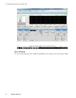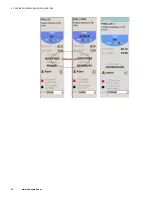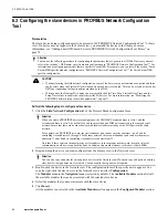
6.3 Configuring the slave devices in PROFIBUS Network Configuration
Tool
Prerequisites
The slave device being configured must to be present in the“PROFIBUS Network Configuration Tool ” Library
view. If a device does not appear in the Library view, you must add the device to the library. For more
information, see “Adding a new GSD-based device to PROFIBUS Network Configuration Tool library” on
page 78.
Attention
You can use the following procedure for configuring the parameters that are generic to all DSBs. However, you must
refer to the sections “<DSB name> specific module configuration in “PROFIBUS Network Configuration Tool ”” for
information on configuring parameters that are specific to each DSB. For example, you can refer to the section “Turck
Excom DSB specific modules configuration in “PROFIBUS Network Configuration Tool ”” for Turck Excom DSB
specific configuration.
CAUTION
•
When performing the field network configuration, some of the devices may not function as expected and there
can be errors when the Protocol Block is loaded when such devices are used. This can be a result of the vendor
GSDs not supporting the functionalities provided by the PGM.
•
When you use the Siemens PA coupler, you must modify the Slot Time, Max. Station Delay Time, and the
Setup Time values to enable the coupler detect the PA devices. For more information, see “Modifying the
PROFIBUS network setup values (bus parameters)” on page 71.
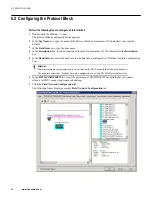
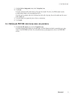
Perform the following steps to configure a slave device
1
Click the
Field Network Configuration
tab of the Protocol Block configuration form.
Attention
When you create a PROFIBUS network configuration, the PROFIBUS master address is set to 1 and the
secondary address is set to 0, by default. If you have more than one PGM pair connected to the same physical
network, ensure that there are no other devices with identical addresses in any of the PGM pairs in the same
network.
For example, in a PROFIBUS network, the first redundant pair can have master addresses 1 and 0 and its
controlling slave addresses 2 through 9. In the same network, the second redundant pair can have the master
addresses 11 and 10 and its controlling slave addresses can start from 12.
Note that if there exists an identical master or slave address in the same physical network, it results in loss of
communication with devices on both the links. In addition, this would warrant a cold reboot of both PGMs.
2
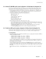
Drag-and-drop the device you must configure from the Library view to the Network view.
Attention
You can also copy and paste the existing slave devices in the Network view. When you copy and paste an existing
slave device, the tag names are also copied. You can modify the tag names, as required.
3
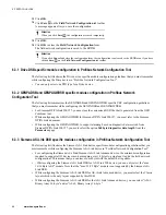
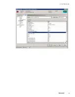
Double-click the device in the Network view. The configuration form of the specific device appears. You
can also right-click the slave device in the Network view and select
Configuration
The
Modules
menu in the
Navigation Area
is selected by default. The
Available Modules
section lists all
the available modules that can be associated with the selected slave device.
4
Select the modules that you must associate with the slave device.
5
Click
Insert
.
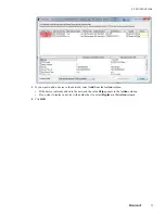
All the modules you selected in the
Available Modules
section appear in the
Configured Modules
section.
6 PROTOCOL BLOCK
64
www.honeywell.com
Summary of Contents for Experion PKS
Page 1: ...Experion PKS PROFIBUS Gateway Module User s Guide EPDOC XX88 en 431E June 2018 Release 431 ...
Page 8: ...CONTENTS 8 www honeywell com ...
Page 10: ...1 ABOUT THIS GUIDE 10 www honeywell com ...
Page 32: ...4 PROFIBUS GATEWAY MODULE PGM INSTALLATION 32 www honeywell com ...
Page 58: ...5 PROFIBUS GATEWAY MODULE PGM BLOCK 58 www honeywell com ...
Page 69: ...6 PROTOCOL BLOCK 69 ...
Page 103: ...5 Click OK 6 PROTOCOL BLOCK 103 ...
Page 110: ...6 PROTOCOL BLOCK 110 www honeywell com ...
Page 183: ...PDC Details tab Figure 6 Detail Display of PDC Details tab 7 DEVICE SUPPORT BLOCK DSB 183 ...
Page 186: ...7 DEVICE SUPPORT BLOCK DSB 186 www honeywell com ...
Page 231: ...9 PROFIBUS I O MODULE PIOMB FUNCTION BLOCK 231 ...
Page 232: ...9 PROFIBUS I O MODULE PIOMB FUNCTION BLOCK 232 www honeywell com ...
Page 236: ...10 PROFIBUS GATEWAY MODULE PGM CONFIGURATION EXAMPLE 236 www honeywell com ...
Page 264: ...13 PROFIBUS GATEWAY MODULE PGM TROUBLESHOOTING 264 www honeywell com ...


