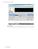
6.3.4 Siemens ET 200M DSB specific module configuration in Profibus Network Configuration Tool
The following list illustrates the Siemens ET200m device specific module configuration guidelines that you
must remember while configuring the Siemens ET200M device in “Profibus Network Configuration Tool”.
• While configuring the Siemens ET200M DSB, you must define configuration slot 1, Configuration slot 2,
and Configuration slot 3 in the slot 1,2, and 3 respectively. You can define the I/O modules from slot 4
onwards in the same order as they are placed in the physical rack.
• You must select the following values for the common parameters.
– Diagnostic Interrupt - Yes
– Process Interrupt - Yes
– Analog-Value format - SIMATIC S7
– Extended diagnostics - Yes
– Start-up for setpoint/act.conf - Yes
– Remove/Insert interrupt - Enable
• While configuring the channel type, channel high and low ranges;
– The slot number parameter can be used to set the physical position of the module on the rack. The slot
number for I/O modules starts from 4. The first three slots are reserved. For example if AI module takes
the first position after the station in the rack, then its slot number is 4.
– The
Diag enable channel
parameters can be used to enable extended diagnostic for the channel.
– The
Meas: Type/Range
parameters can be used to select signal type for the channel.
6.3.5 Turck Excom DSB specific modules configuration in Profibus Network Configuration Tool
The following sections illustrate the Turck Excom device specific module configuration guidelines that you
must remember while configuring the Truck Excom device in “Profibus Network Configuration Tool”.
For reading HART data
• For configuring the Turck Excom DSB to read HART data, you can configure the I/O modules AIH40Ex or
AIH41Ex or AOH40Ex as follows.
– AIH40Ex/AIH41Ex/ AOH40Ex - Process data + 1 HART data
– AIH40Ex/AIH41Ex/ AOH40Ex - Process data + 4 HART data
– AIH40Ex/AIH41Ex/ AOH40Ex - Process data + 8 HART data
If you are using the output module, AOH40Ex, you must configure two net tag names; one for the process
data and one for the HART data. However, if you are using the input module, AIH40Ex or AIH41Ex, you
must configure only one net tag name.
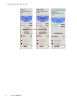
While configuring the module-specific parameters in the
Parameters
page, you can note that for each
channel, the first secondary variable value is set to “
on
” and the remaining three secondary variable value is
set to “
off
.” You can modify this as required based on from which secondary variable you want to read the
HART data.
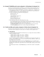
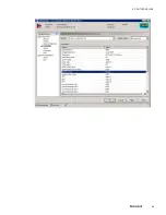
The following figure illustrates a sample
Parameters
page of a module that is capable of reading HART
data.
6 PROTOCOL BLOCK
67
Summary of Contents for Experion PKS
Page 1: ...Experion PKS PROFIBUS Gateway Module User s Guide EPDOC XX88 en 431E June 2018 Release 431 ...
Page 8: ...CONTENTS 8 www honeywell com ...
Page 10: ...1 ABOUT THIS GUIDE 10 www honeywell com ...
Page 32: ...4 PROFIBUS GATEWAY MODULE PGM INSTALLATION 32 www honeywell com ...
Page 58: ...5 PROFIBUS GATEWAY MODULE PGM BLOCK 58 www honeywell com ...
Page 69: ...6 PROTOCOL BLOCK 69 ...
Page 103: ...5 Click OK 6 PROTOCOL BLOCK 103 ...
Page 110: ...6 PROTOCOL BLOCK 110 www honeywell com ...
Page 183: ...PDC Details tab Figure 6 Detail Display of PDC Details tab 7 DEVICE SUPPORT BLOCK DSB 183 ...
Page 186: ...7 DEVICE SUPPORT BLOCK DSB 186 www honeywell com ...
Page 231: ...9 PROFIBUS I O MODULE PIOMB FUNCTION BLOCK 231 ...
Page 232: ...9 PROFIBUS I O MODULE PIOMB FUNCTION BLOCK 232 www honeywell com ...
Page 236: ...10 PROFIBUS GATEWAY MODULE PGM CONFIGURATION EXAMPLE 236 www honeywell com ...
Page 264: ...13 PROFIBUS GATEWAY MODULE PGM TROUBLESHOOTING 264 www honeywell com ...


