Chapter 4 - ControlNet Network Component Installation
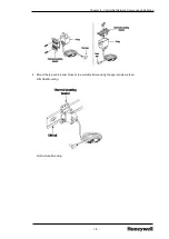
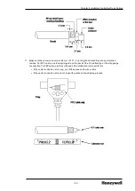
To identify the drop-cables
1. After installing your tap, locate the drop-cable identifying labels in your tap kit.
2. Apply labels as follows:
l
Apply one red A label at the Supervisory ControlNet (A) drop cable connector.
l
Apply one yellow B label at the Supervisory ControlNet (B) drop cable connector.
l
Apply two red A labels at the I/O ControlNet (A) drop cable connector.
l
Apply two yellow B labels at the I/O ControlNet (B) drop cable connector.
3. If desired, you may use this marking code system for module connections, taps, and trunk cables.
4. Save any unused labels for future use.
4.3
Installing Repeaters
The following general rules must be applied when mounting either the model 9904-RPT or the model
9904-RPTD:
l
Air flow, in/out of the air holes on the top and bottom of the repeater, for proper ventilation, must not
be impeded. Make sure there is a minimum of 5.1 cm (2 in) from surrounding equipment.
l
For proper ventilation, air flow through holes on the top and bottom of the repeater must not be
blocked. Make sure NEMA enclosures must be employed in environments where protection from
dust, moisture or corrosive atmospheres is required.
l
Mount to a grounded metal plate if possible.
For more details on selecting where to use repeaters, refer to the Control Hardware Planning Guide,
Connecting your Links and Segments.
l
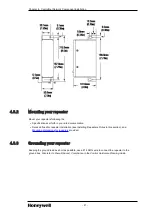
Mounting dimensions for repeaters
l
l
l
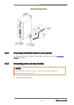
Connecting ControlNet cables to your repeater
l
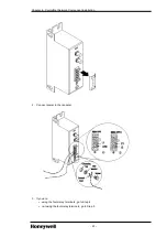
Connecting power and relay circuitry
4.3.1
Mounting dimensions for repeaters
Figure 4.1 Repeater mounting dimensions
- 20 -

