background image

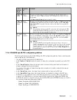
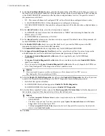
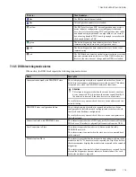
• If you have selected the DM80Ex digital module, in the 

Channel Number 

column, you must enter the

channel number. You must enter the channel number from 0 through 7. For other modules, the channel
number is automatically updated.

• In the 

Input Signal Type 

column, you must select the signal type supported for the AI module . This

parameter is available for configuration only when you select the PDC type as 

AI

.

– When you select the signal type as 

Not Configured

, this turns off the specified channel. The inputs on

this channel are not processed. You must select this value for all unused channels.

– When you select any signal type other than 

Not Configured

, the values of the CHHIGHRANGE and

CHLOWRANGE parameters are updated based on their channel high and low values.

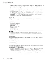
• In the 

Output Signal Type 

column, you must select the signal type supported for the AO module . This

parameter is available for configuration only when you select the PDC type as 

AO

.

– When you select the signal type as 

Not Configured

, this turns off the specified channel. The inputs on

this channel are not processed. You must select this value for all unused channels.

– When you select any signal type other than 

Not Configured

, the values of the CHHIGHRANGE and

CHLOWRANGE parameters are updated based on their channel high and low values.

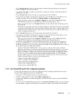
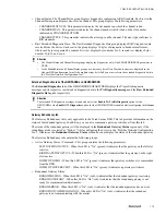
• With R410, you can modify the values of the following parameters even after a PDC is associated and

connected to a PIOMB. However, you must ensure that you reload both the DSB and the PIOMB after
modifying the parameter value. If you do not reload both the DSB and the PIOMB, there may be a break in
the connection between the DSB and the PIOMB.
– Number of Channels (NUMCHANNEL) - You can increase or decrease the Number of Channels

parameter value. There is no restriction on increasing the number of channels. However, if you want to
decrease the number of channels, you can decrease the number only until the last assigned channel
number. For example, consider a scenario where you have entered the number of channels of a PDC as
10. However, you have assigned only 6 channels (channel 0 through channel 5) to the PROFIBUS
channels. In this scenario, you can reduce the Number of Channels value to 6. If you try to reduce the
Number of Channels value to 5 or less an error message appears.

– Channel Description (CHDESCRIPTION)
– Channel Low Range (CHLOWRANGE)
– Channel High Range (CHHIGHRANGE)
– Input Signal Type (INPUTSIGNALTYPE)
– Output Signal Type (OUTPUTSIGNALTYPE)
– Channel Number (CHNNUMBER)

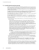
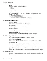
7.16.8  Guidelines for configuring Turck Excon DSB for reading HART data

• To configure the Turck Excom DSB to read HART data in addition to process data, you must configure the

PDCs based on the IO module.
– If you are using an output module, you must configure two PDCs; one for the process data and one for

the HART data.

– If you are using an input module, you must configure only one PDC.

• To read the process data, you must select the appropriate PDC type (AIH40Ex/AIH41Ex/ AOH40Ex) and

associate the corresponding net tag name.

• To read HART data, you must select the 

HARTInputData 

PDC and associate the corresponding net tag

name. When you select the 

HARTInputData 

PDC type, you must enter the number of channels in the

Number of Channels 

column as 1, 4, or 8 as the modules can be configured for reading 1, 4, or 8 HART

data.

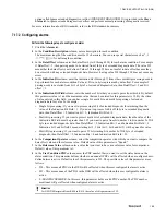
• When you enter the number of channels for reading HART data, the lower grid becomes editable. You must

enter the physical channel number from where the HART data needs to be read. The physical channel
numbers start from 0.

7  DEVICE SUPPORT BLOCK (DSB)

164

www.honeywell.com

Summary of Contents for Experion PKS

Page 1: ...Experion PKS PROFIBUS Gateway Module User s Guide EPDOC XX88 en 431E June 2018 Release 431 ...

Page 2: ...f Honeywell International Sarl While this information is presented in good faith and believed to be accurate Honeywell disclaims the implied warranties of merchantability and fitness for a purpose and makes no express warranties except as may be stated in its written agreement with and for its customer In no event is Honeywell liable to anyone for any direct special or consequential damages The in...

Page 3: ...4 6 3 Redundant PGM in a non redundant Profibus cabling 30 5 PROFIBUS Gateway Module PGM Block 33 5 1 PGM overview 34 5 1 1 PGM block creation 34 5 1 2 PGM block deletion 34 5 2 Configuring a PGM 35 5 3 Configuring a secondary PGM 36 5 4 Converting a redundant PGM to a non redundant PGM 37 5 5 Monitoring PGM block 38 5 5 1 PGM block state after configuration and load 38 5 5 2 PGM block status para...

Page 4: ...ddress 76 6 4 5 Changing the master settings 76 6 4 6 Detecting slave devices in the network 76 6 5 Adding a new GSD based device to PROFIBUS Network Configuration Tool library 78 6 6 About grouping adjacent modules into one logical module 79 6 6 1 Guidelines for grouping modules 79 6 6 2 About the Address Management page 80 6 6 3 Grouping adjacent modules into one logical module 82 6 6 4 Ungroupi...

Page 5: ... DSB 134 7 8 1 Functions of Siemens AS i Link 134 7 9 Siemens ET200M Device Support Block Siemens ET200M DSB 138 7 9 1 I O modules supported by the Siemens ET200M DSB 138 7 9 2 Functions of Siemens ET200M DSB 140 7 10 Turck Excom Device Support Block Turck Excom DSB 142 7 10 1 I O modules supported by the Turck Excom DSB 143 7 10 2 Functions of Turck Excom DSB 144 7 11 UDT support for DSB blocks 1...

Page 6: ... auto discovery of HART devices 199 8 6 Monitoring the PBHCHANNEL block 201 8 6 1 PBHCHANNEL HART Status related parameters 201 8 6 2 PBHCHANNEL HART Notification related parameters 202 8 6 3 PBHCHANNEL HART Variables related parameters 202 8 6 4 PBHCHANNEL HART Identification related parameters 203 8 6 5 HART alarms events processing 204 8 6 6 HART alarms event regeneration 205 8 7 PBHIOMB block ...

Page 7: ... 249 13 1 Behavior of PGM during fault scenarios 250 13 1 1 Loss of communication between PGM and C300 250 13 1 2 Loss of communication between PGM and slave device 250 13 1 3 Loss of communication between the PGM and control strategies 251 13 1 4 CEEC300 state is changed to Idle 251 13 1 5 Inactivation of PIOMB 251 13 1 6 Deletion of PIOMB 251 13 1 7 PGM power failure 252 13 1 8 Removal of PGM fr...

Page 8: ...CONTENTS 8 www honeywell com ...

Page 9: ...on related to a block is available in one chapter For example the PROFIBUS I O Module PIOMB Function Block chapter contains the following information related to PIOMB block PIOMB block overview PROFIBUS I O channel blocks Functioning of PIOMB Configuring a PIOMB Monitoring a PIOMB PIOMB block station displays Revision history Revision Date Description A February 2015 Initial release of the documen...

Page 10: ...1 ABOUT THIS GUIDE 10 www honeywell com ...

Page 11: ... Periphery DP is the most frequently used PROFIBUS communication profile It is optimized for speed efficiency and low connection costs and is designed especially for communication between automation systems and distributed peripherals PROFIBUS DP Overview PROFIBUS DP is a master slave token passing network which utilizes a request response protocol Basic data exchange operations ensure that on a p...

Page 12: ...bout DPV1 and HART enhancements for PGM on page 14 PGM topology on page 15 PGM data flow diagram on page 17 Data communication in PGM on page 18 2 PROFIBUS GATEWAY MODULE PGM OVERVIEW 12 www honeywell com ...

Page 13: ...US devices over the PROFIBUS network The main purpose of using PDA is for fast I O protocol data transfer that provides optimized peer to peer communications between the PGM and the C300 Controller over FTE Process Data Collection PDC A data structure that can store and map several input or output process data items channels from a given slave device to one or more PIOMB blocks in the C300 Control...

Page 14: ...the cyclic process data Acyclic data transfer exists wherever slave devices provide several parameterization options during operation Typically the parameters of a device such as limit values rotational speed or torque operation mode generation of an error list and generating alarms are parameterized during operation HART enhancements PGM is enhanced to support HART over PROFIBUS profile The PBHIO...

Page 15: ...following figure depicts the non redundant PGM topology The following figure depicts the non redundant PGM PROFIBUS topology The following figure depicts the redundant PGM topology 2 PROFIBUS GATEWAY MODULE PGM OVERVIEW 15 ...

Page 16: ...ROFIBUS topology Attention The wiring diagrams provided in the PGM architecture and topology section is used for illustration purposes only and is not the recommended way of PROFIBUS cabling 2 PROFIBUS GATEWAY MODULE PGM OVERVIEW 16 www honeywell com ...

Page 17: ...2 4 PGM data flow diagram The following figure depicts the data flow through the various components and blocks in the PGM architecture 2 PROFIBUS GATEWAY MODULE PGM OVERVIEW 17 ...

Page 18: ...PBHCHANNEL Process data access DPV1 data record access PDC Configuration data flow HARTdata access HART communication DPV1 communication CDA communication PDA communication DPV0 communication PDC configuration flow PDC configuration flow CDA communication CDA communication DPV1 communication CDA communication Figure 1 Data communication between C300 Controller PGM slave devices and the HART module...

Page 19: ...or a brief overview of the Series C control hardware PGM model details and PGM performance data For more information on the PROFIBUS technology you must refer to the PROFIBUS website For more information on the PROFIBUS devices you must refer to the vendor specific manuals Related topics Review Experion system capabilities on page 20 19 ...

Page 20: ...ntrollers Refer to the Control Hardware Planning Guide for a general discussion of planning activities for Experion control hardware that covers the following Initial planning and design Control network considerations Control hardware configuration Site selection and planning Control processing considerations Application licensing considerations Refer to the PROFIBUS Interface Implementation Guide...

Page 21: ...M Installation Related topics Pre installation considerations on page 22 PGM assembly on page 23 PGM IOTA pinouts on page 24 Installing a PGM on page 26 PGM power on and startup on page 28 Profibus cabling guidelines on page 29 21 ...

Page 22: ...e guidelines when you handle any electronic component Touch a grounded object to discharge static potential Wear an approved wrist strap grounding device Do not touch the wire connector or connector pins Do not touch circuit components inside a component If available use a static safe workstation When not in use keep the component in its static shield box or bag Industry standard means of terminat...

Page 23: ...NDEX 100 10 1 Three rotary decimal switches used to set the FTE network address Device Index of the PGM 4 2 1 CF9 control firewall 9 port control firewall CF9 In the control cabinet Control Firewall assemblies CF9 provide connection of control hardware PGM and C300 Controllers to the FTE network STP CAT5 cables connect the FTE capable control hardware to the Control Firewall IOTA Two Control Firew...

Page 24: ...ve Transmit data minus A wire green color 9 Not Connected Note Only the signals shown in the above figure and table are available for PGM Others are not connected The metallic shell shall be used as the primary shield and protective ground connection as it provides the best EMI mitigation Pin 1 is provided for compatibility with older systems that use this pin as a shield connection point VP 5V an...

Page 25: ...nd State 3 result in the same LED indication Condition described in State 2 only occurs during configuration loading Condition described in State 3 is a result of the connectivity problem or PROFIBUS device failure Therefore this condition can occur at any time during routine operation LED behavior for secondary PGM Table 2 LED behavior for secondary PGM State Color LED Indication Description 1 Gr...

Page 26: ...OTA is facing up CAUTION Do not fully tighten the IOTA mounting screws before installing and tightening the power and ground screws 24V and COM terminals which can bind during installation or removal Follow instructions carefully 4 Position the assembled IOTA board at the proper mounting location 5 Thread the four mounting screws only half way to attach the IOTA board to the channel 6 Tighten the ...

Page 27: ...ir configured Device Indexes If the Device Index switches on a primary or a non redundant PGM IOTA are set to an even number address or do not match the configured Device Index then an error is generated when loading the controller and the load operation is aborted 12 Insert the PGM module onto IOTA board making sure that the PGM circuit board is aligned properly with the IOTA board connector Secu...

Page 28: ...ndicators displays are identical to the C300 controller faceplate indicators displays The front panel of the PGM has four LEDs The module also has a four character display that indicates the state of the module Tip For detailed information on faceplate indicators displays refer to the C300 faceplate indicators displays section and C300 faceplate display indications section in the C300 Controller U...

Page 29: ...GM in a non redundant Profibus cabling on page 30 4 6 1 Copper cable based media redundancy The following diagram illustrates the copper cable based Profibus topology In this topology DP cable A and DP cable B are the redundant backbone network To this network the switch slave supporting media redundancy can be directly connected This network can have non redundant segment like the ones on the lef...

Page 30: ...re redundant or non redundant segment are connected through OLM modules Attention Terminators are very important for copper segments All Copper segments must use external terminator units 4 6 3 Redundant PGM in a non redundant Profibus cabling The following diagram illustrates a topology of a redundant PGM in a non redundant Profibus cabling scenario 4 PROFIBUS GATEWAY MODULE PGM INSTALLATION 30 w...

Page 31: ...ortant for copper segments All Copper segments must use external terminator units CAUTION Avoid using diagnostic LED PROFIBUS connector and enabling termination in the plug connected to PGM 4 PROFIBUS GATEWAY MODULE PGM INSTALLATION 31 ...

Page 32: ...4 PROFIBUS GATEWAY MODULE PGM INSTALLATION 32 www honeywell com ...

Page 33: ...figuring a PGM on page 35 Configuring a secondary PGM on page 36 Converting a redundant PGM to a non redundant PGM on page 37 Monitoring PGM block on page 38 PGM redundancy specific operations on page 42 PGM shutdown operations on page 48 PGM block station displays on page 50 33 ...

Page 34: ...ork The secondary PGM considers the network as healthy if it has established a PROFIBUS communication with the primary PGM The secondary PGM does not communicate with the slave devices at all The secondary PGM only checks if a device with the configured master address participates at token exchange active and passive PROFIBUS master exchange token between each other HART device support in PGM PGM ...

Page 35: ... the check box the secondary tag name appears in the Redundancy Configuration box The secondary PGM block is added when the primary PGM block configuration form is closed 6 In the CPU Free Low Alarm box type the value at which an alarm is to be generated when the available CPU resources fall less than this limit Attention Do not set the CPU Free Low Alarm value lower than the default value of 20 T...

Page 36: ...t click the secondary PGM block icon and select Module Properties The secondary PGM configuration form appears 2 In the Tag Name box type the name of the secondary PGM block a maximum of 16 characters or accept the default 3 In the Item Name box type the item name 4 Use the online help as a guide to complete the configuration entries on all other tabs 5 Click OK 5 PROFIBUS GATEWAY MODULE PGM BLOCK...

Page 37: ...nization between the primary and secondary PGM terminates A Not Synchronized diagnostic alarm is generated by both the primary and the secondary PGM 4 Delete the secondary PGM function block from the Monitoring view 5 Disconnect the redundancy cable from the primary PGM 6 Remove the secondary PGM hardware by removing the PGM module and its IOTA 7 In the Project view right click the primary PGM and...

Page 38: ...ATE The BCMSTATE parameter displays the PGM platform state Redundant Synchronization State RDNSYNCSTATE The RDNSYNCSTATE parameter displays the current synchronization state of the PGM Redundancy Role RDNROLESTATE The RDNROLESTATE parameter indicates whether the module is operating as a primary secondary or logically non redundant PGM 5 5 3 PGM block command parameters PGM Command BCMCOMMAND The B...

Page 39: ...ace The following parameters are used for displaying the memory descriptors Total Memory Descriptors NTOTMEMDESC Used for indicating the total number of memory descriptors This is a static number and the units are number of descriptors Free Memory Descriptors NUMFREEDESC Used for indicating the number of free or available memory descriptors Registered Memory Descriptors NUMREGDESC Used for indicat...

Page 40: ...visible No Database red PGM is non redundant and not communicating Offnet red white Primary PGM is not communicating Offnet white red Secondary PGM is not communicating Offnet 5 5 6 PGM block diagnostic alarms When active the PGM block reports the following diagnostic alarms Attention In a redundant PGM if a PB Link failure occurs in the secondary PGM the secondary PGM does not generate an alarm o...

Page 41: ... affect the control strategies and there is no loss of data However a soft fail is generated Attention If the PGM is powered off and on the PGM clears it memory database and also clears the device index value Duplicate Device Index alarm This alarm is reported when the device index of the secondary PGM is identical to the device index of another node FTE A B cable Fault Alarm This alarm is reporte...

Page 42: ...of the I Os plays a vital role Conditions that result in a switchover The following conditions result in a switchover Issuing a Switchover command Issuing a Shutdown command on the primary PGM Both FTE cables removed from the primary PGM The primary PGM is removed from the IOTA The primary PGM is restarted The primary PGM is failed The PROFIBUS cable is disconnected from the primary PGM Conditions...

Page 43: ...RDNDELAYMAX Max Initial Sync Time RDNISTIMEMAX Max Switchover Time RDNSOTIMEMAX Related topics Enabling Synchronization on page 43 Disabling Synchronization on page 44 Configuring the network for switchover on page 44 Enabling a secondary PGM to become a primary PGM in the absence of a partner module on page 46 Performing a manual switchover on page 46 PGM redundancy notifications on page 47 5 6 1...

Page 44: ... most of the slave devices you can configure a time during which they keep their outputs However some devices lose their outputs immediately Therefore the PROFIBUS field network must be configured to tolerate this brief absence of the master during switchover If this configuration is not performed the device outputs can drop Attention While configuring the network for switchover DPV1 must be disab...

Page 45: ...or a slave device the Watchdog control time and Data control times must be about three times longer than the actual time when DP V1 is disabled By default the ET200M devices have DP V1 enabled The following table lists the recommended baud rates and their corresponding Watchdog Control Time and Data Control Time Baud Rate Watchdog Control Time Data Control Time 1500 1000 6000 500 1000 6000 187 5 2...

Page 46: ...itoring view Perform the following steps to enable a secondary PGM to become a primary PGM in the absence of a partner module 1 In the Monitoring view double click the primary PGM icon The PGM block configuration form appears 2 Click the Redundancy tab 3 Click Become Primary 4 Click Yes to confirm the action Confirm that the secondary module assumes the primary role The old primary module should b...

Page 47: ...d and re connected after sometime Redun Partner Visible on Redun Link Both the primary and the secondary PGM generate this notification upon detecting a compatible partner visible across the redundancy private path Redun Sync In Progress Both the primary and the secondary PGM generate this notification after both FTE cables are removed and re connected and the initial synchronization is started Re...

Page 48: ...devices that are on control The PGM will not accept the SHUTDOWN command if it has DSB blocks loaded to either of its links The Enable Shutdown is a means to override that Therefore caution MUST be exercised when selecting the Enable Shutdown check box Tip In a redundant pair when the primary PGM FB is shutdown the secondary PGM assumes the role of the primary You can monitor this change by observ...

Page 49: ...3 In the Main tab click Shutdown in the Controller Command list The secondary PGM FB is shutdown This results in the PGM to work as a non redundant PGM 5 PROFIBUS GATEWAY MODULE PGM BLOCK 49 ...

Page 50: ...a_fp htm Redundancy tab sysdtlPGM2b htm Soft Failures tab sysdtlPGM2c htm Configuration Details tab sysdtlPGM2d htm 5 8 2 Calling up the displays The following table lists the actions that you must perform to call up the PGM block detail displays To call the PGM block Then Main tab display Type the point name for example PGM2_325 in the Station command zone and press F12 You can also click the Sea...

Page 51: ...licking the hyper link provided for the PBLink_ blocks Figure 2 PGM Main tab display You can modify the following values from the PGM Main tab detail display Alarm Enable State Temperature Threshold this is not available in the secondary module detail display Stack exceeded alarm Controller Command Reset Statistics this is a push button Attention The Main tab detail display of the redundant PGM is...

Page 52: ... functions from the PGM Redundancy tab detail display Disable Synchronization Enable Synchronization Become Primary Initiate Switchover Tip These parameters appear as push buttons in the detail display Attention For a non redundant PGM the text Non Redundant appears in the Redundancy tab detail display Soft failure tab The Soft failures tab detail display provides information on the soft fails tha...

Page 53: ... communication error all the LEDs in the Soft Failure tab appear gray Config Details tab The Config Details detail display is identical to the Main tab of the PGM block from Control Builder 5 PROFIBUS GATEWAY MODULE PGM BLOCK 53 ...

Page 54: ...ng Enabled Controller Command Temperature High Alarm CPU Free Low 5 8 4 PGM group detail display system status display group trend display Group detail displays You can configure the group with PGM PBLINK and PIOMB faceplates 5 PROFIBUS GATEWAY MODULE PGM BLOCK 54 www honeywell com ...

Page 55: ...Group Trend display You can configure the group trend with PGM PBLINK and PIOMB faceplates 5 PROFIBUS GATEWAY MODULE PGM BLOCK 55 ...

Page 56: ...System Status display You can view the faceplates of PGM PBLINK and PIOMB on the status pane of the System Status Display 5 PROFIBUS GATEWAY MODULE PGM BLOCK 56 www honeywell com ...

Page 57: ...nowledge the alarms from the faceplate In addition the operators can issue the SHUTDOWN command from the faceplate The following figure displays the faceplate of a redundant and non redundant PGM 5 PROFIBUS GATEWAY MODULE PGM BLOCK 57 ...

Page 58: ...5 PROFIBUS GATEWAY MODULE PGM BLOCK 58 www honeywell com ...

Page 59: ...FIBUS Network Configuration Tool library on page 78 About grouping adjacent modules into one logical module on page 79 About modifying the field network configuration during runtime on page 86 Export import of field network configuration on page 88 Audit Trail for field network configuration on page 89 Monitoring Protocol Block on page 91 Monitoring the field network configuration on page 94 QVCS ...

Page 60: ...y Similarly you cannot delete a Protocol Block individually You must delete the parent PGM block to delete the Protocol Block 6 1 1 Profibus Network Configuration Tool The Profibus Network Configuration Tool is used for configuring the field network devices on the PROFIBUS gateway The Protocol Block configuration form is the host tool and the Profibus Network Configuration Tool is an ActiveX compo...

Page 61: ...lves the following steps 1 Configuring the slave devices in PROFIBUS Network Configuration Tool on page 64 2 Configuring the master in Profibus Network Configuration Tool on page 70 Attention If you are migrating a PGM from R410 1 or earlier you must manually install SYCON net_Honeywell_setup exe as per the Installation Instructions document This document is available in the R410 2 support media i...

Page 62: ...iption box 5 In the Baud Rate list select the baud rate for the link that is configured in Profibus Network Configuration Tool Attention You must configure this parameter only for calculating the DPV1 bandwidth based on the baud rate The baud rate selected at Profibus Network Configuration Tool and PB_LINK must be identical 6 In the DPV1BANDWIDTH list select the percentage of PROFIBUS DP bandwidth...

Page 63: ...nformation on configuring a field device refer to Using Profibus Network Configuration Tool for configuring field network devices on page 61 8 Use the online help as a guide to complete the configuration entries on all other tabs 9 Click OK 6 PROTOCOL BLOCK 63 ...

Page 64: ...nfiguration form Attention When you create a PROFIBUS network configuration the PROFIBUS master address is set to 1 and the secondary address is set to 0 by default If you have more than one PGM pair connected to the same physical network ensure that there are no other devices with identical addresses in any of the PGM pairs in the same network For example in a PROFIBUS network the first redundant...

Page 65: ...in this list may vary based on the DSB selected 8 Select the I O module from the Module list 9 Configure the channel type and the channel s high and low ranges Refer to the following figure for an example of configuring the analog module parameters Attention You must perform this step if you have selected the analog I O modules 10 Similarly select the other I O modules from the Module list and con...

Page 66: ...B for Siemens DP PA Link IM 157 you must refer to the Siemens DP PA Link document While configuring the GENPAGWDSB to support alarming based on diagnostic data received from Siemens DP PA Link IM 157 you must select the option 160 byte diagnostics data length from the Parameters page 6 3 3 Siemens ASi Link DSB specific modules configuration in Profibus Network Configuration Tool The following list...

Page 67: ...enable extended diagnostic for the channel The Meas Type Range parameters can be used to select signal type for the channel 6 3 5 Turck Excom DSB specific modules configuration in Profibus Network Configuration Tool The following sections illustrate the Turck Excom device specific module configuration guidelines that you must remember while configuring the Truck Excom device in Profibus Network Co...

Page 68: ...tion capability of the redundant gateway is not verified on switchover and diagnostic data for gateway is not generated Therefore you cannot view the status of the redundant gateway in the Redundant Gateway tab from the Monitoring view When the redundancy mode is set to mode 1 the communication capability of the redundant gateway is verified on switchover and diagnostic data for gateway is generat...

Page 69: ...6 PROTOCOL BLOCK 69 ...

Page 70: ...nt details appear in the right pane 3 Perform the following as required Assigning the device to the correct hardware on page 70 Modifying the PROFIBUS network setup values bus parameters on page 71 Configuring the field network tag names on page 72 Changing the field network device address on page 76 Grouping adjacent modules into one logical module on page 82 Changing the master settings on page ...

Page 71: ...chip type the serial number and the access path is displayed 3 Select the check box against the device that you must assign 4 Click Apply 6 4 2 Modifying the PROFIBUS network setup values bus parameters 1 Click the Bus Parameters menu in the Navigation Area The Bus Parameters details appear in the right pane The Bus Parameters details contain the main setup values of the PROFIBUS network For more ...

Page 72: ...ces have DP V1 enabled When you select the Baud Rate as 45 45 the values of the following parameters are updated by default Slot Time 100 Max Station Delay Time 60 Setup Time 1 The Siemens PA coupler supports only the 45 45 BR Though they support the 45 45 BR the default values of the Slot Time Max Station Delay Time and the Setup Time do not enable the coupler to detect the PA devices Therefore w...

Page 73: ... Whenever you reconfigure net tags for a PDC you must reload the DSB before removing the same net tag in Sycon and reloading the Protocol Block This prevents the DSB or the PDC from going into error state during run time while modifying the net tag usage 1 Click the Process Data menu in the Navigation Area The slave devices that you have selected appear in the right pane 2 Click to view the input ...

Page 74: ... associated with the specific PPO type Attention The PKW and cyclic data areas appear separated from each other Based on the number of PKW and cyclic data areas you must configure the network tag names In the example above there are two inputs PKW inputs and Cyclic inputs and two outputs PKW outputs and Cyclic outputs Therefore you must configure four PDCs to access this data 3 Configure the PKW i...

Page 75: ...et tag names for a single byte of data This tag name must refer to the entire 4 byte area with the tag name referring to its own byte plus the 3 byte with the default names In the above figure net tag Slv1_7Out refers to its own byte plus the 3 bytes with the default names Output_2 Output_3 and Output_4 Similarly the net tag Slv16_23In refers to its own byte plus the 3 bytes with the default names...

Page 76: ...gs The master settings appear in the right pane 2 Change the watchdog time if required in the Watchdog time box 3 Click Apply 6 4 6 Detecting slave devices in the network You can detect all the physical slave devices in the network from the Field Network Configuration tab of the Protocol Block This can be accomplished by performing a Network Scan This scan lists all the physical slave devices conn...

Page 77: ...k select Add from the Action column If the device is already added to the network the value Skip appears in the Action column If you want to replace a device with another device select Replace in the Action column 4 Click OK 6 PROTOCOL BLOCK 77 ...

Page 78: ...pplication Data SYCONnet PROFIBUS GSD For Windows 7 use the following directory C ProgramData SYCONnet PROFIBUS GSD Attention You must copy only one version of the device GSD to the defined directory If different versions languages are copied you will see the device as many times in the PROFIBUS Network Configuration Tool library If the same device exist several times in the PROFIBUS Network Confi...

Page 79: ... consecutive addresses and there must not be any empty slot in between the grouped modules You can configure the input modules as one group and the output modules as another However you cannot configure both input and output modules as one group You can group bidirectional modules as groups However you cannot group unidirectional and bidirectional modules as one group When grouping bidirectional m...

Page 80: ...d for HART data should not be grouped For example if a module is configured for both process data and HART data then such a module can not be part of a grouped module If the same is configured only for process data then the module can be grouped Note that for Turck Excom device the channel numbering always starts from 1 6 6 2 About the Address Management page In Experion R410 1 or earlier the Addr...

Page 81: ...etes the corresponding grouped virtual module Add reserved area Enables you to add a contiguous memory area as reserved area for a slave device By default reserved memory space for each slave is 128 bytes However you can modify this based on your requirement Maximum space available is 244 bytes for each input or output Del reserved area Enables you to free unnecessary reserved memory area Lock all...

Page 82: ...le click the master in the Network view 3 Click Address Management in the Navigation area The Address Management page appears 4 Click to view the input and output modules associated with the specific device 5 Select the adjacent modules that must be grouped into one logical group The following figure displays a sample Address Management page in which two adjacent modules are selected for grouping ...

Page 83: ...ollowing figure displays a sample virtual tag name for the grouped modules Attention You cannot group IO modules if one or more IO modules have PDC references in DSB The network configuration tool does not display any error message if you group IO modules that have PDC references in DSB Also when you group such modules the status bar displays the status as save operation succeeded and also the vir...

Page 84: ...ved area button changes to Del reserved area button and vice versa You can click the Del reserved area button to remove the unnecessary reserved memory area Attention Maximum space available for a configured module is 244 bytes for an input or an output When 244 bytes are configured and if you try to add reserved memory space an error message appears indicating that no reserved memory can be added...

Page 85: ... Apply 6 Click OK to close the Address Management page 7 Click OK to close the Field Network Configuration tab 6 6 7 About the Signal Configuration page After you have configured the slave devices in the master you can view the device details such as the slot number device type tag name data type and so on from the Signal Configuration page The following figure displays a sample Signal Configurati...

Page 86: ...separately This helps you to add modules without unlocking the slaves The length of the reserved area gets adjusted automatically with the memory area of the module on insertion of a module This way the Target Token Rotation Time TTRT is maintained and as a result the change can be loaded to the PGM without causing process data delivery interruptions to unchanged slaves in the network As long as t...

Page 87: ...laves before modifying the configuration to use the HCiR feature This prevents any re arrangement of the Profibus Network Configuration Tool address management Modifying the configuration includes adding or deleting modules Keep all slaves in the Protocol Block locked all the time Unlock them when there is no reserved memory area planned for the device and modification in the configuration is requ...

Page 88: ... of the Protocol Block in which you have performed the field network configuration 2 Click Export on the Field Network Configuration tab toolbar The Save As dialog box appears 3 Select the location where you want to store this dat file 4 Type a name for the configuration file 5 Click Save 6 8 2 Importing field network configuration When you perform an import of the field network configuration the ...

Page 89: ... the time period during which the Field Network Configuration tab of the Protocol Block is opened and closed Each session is identified by a unique session ID along with the logged in user name If you make any changes to the network configuration during a session the changes that you have made appears under the respective session The buttons in the Audit Trail tab can be used to expand collapse Au...

Page 90: ...twork configuration changes that you made till V3 00 QVCS Compare When you perform a QVCS Compare operation the Diff Tool displays the ERDB AUDITTRAIL parameter in highlighted mode The status appears as M if the data has been modified between the selected versions In addition the message Please refer to module properties of this block to see the parameter value appears in the parameter value Atten...

Page 91: ... status will be STOPPED If the network configuration is not created the status will be IDLE The Slave State SLAVESTATE will be OK indicating that the master is in cyclic data exchange with all the configured slave devices If there is at least one slave device missing or if the slave device has a diagnostic request pending the status will be FAILED Global State Field GLOBALSTATE If there is a notif...

Page 92: ...tistics information related to the DPV1 connection is monitored from the Class 2 Connection Status table DPV1 Bytes per sec DPV1BYTESPERSEC The DPV1 Bytes per sec DPV1BYTESPERSEC parameter provides the DPV1 traffic in bytes per second per link level DPV1 Requests per sec DPV1REQSPERSEC The DPV1 Requests per sec DPV1REQSPERSEC parameter provides the DPV1 traffic in requests per second HOP and DPV1 ...

Page 93: ...N is calculated It is then compared to the value that was loaded along the NETTAGTABLEBIN parameter If there is a mismatch in this comparison this notification is generated You must modify and reload the field network configuration for this notification to return to normal Input Data Base Cycle Changed The input data is sampled on every Process Data Access PDA base cycle which is the smallest raw ...

Page 94: ...nosis on page 94 Viewing the status of all slave devices from the Profibus Network Configuration Tool Network view on page 95 Viewing the slave devices from the Life List menu on page 96 Changing the device address from the Set Station Address menu on page 97 Detecting slave devices in the network on page 76 Viewing the slave device diagnosis on page 100 Viewing the slave device s extended diagnos...

Page 95: ...f configured slave devices and number of slave devices that have diagnostics 5 Similarly you can select the appropriate diagnosis menus in the Navigation Area to view the appropriate diagnostics 6 Click OK 6 11 2 Viewing the status of all slave devices from the Profibus Network Configuration Tool Network view Perform the following steps to view the status of all slave devices from the Profibus Net...

Page 96: ...s not connected 6 11 3 Viewing the slave devices from the Life List menu Right click the master and select Addition Functions Life List The Life List window displays the slave devices that are connected to the network 6 PROTOCOL BLOCK 96 www honeywell com ...

Page 97: ...ield Network Configuration tab of the Protocol Block Perform the following step to change the device address from the Set Station Address menu 1 Click the Field Network Configuration tab of the Protocol Block in which you have configured the slave device and the master 2 Right click the master and select Addition Functions Set Station Address The Set Station Address dialog box appears The followin...

Page 98: ...tion address box 4 Click Set Address If the change is successful you can view the new station address in the Life List window The following figure displays the station address as 15 after changing the address 6 PROTOCOL BLOCK 98 www honeywell com ...

Page 99: ...device is not added to the network Perform the following steps to detect all slave devices in the network 1 Click the Field Network Configuration tab of the Protocol Block in which you have configured the master and the slave device 2 Right click the master and select Network Scan Attention If you have not assigned the device to the hardware an message appears The netDevice window appears as displ...

Page 100: ...vice diagnosis Perform the following steps to view the slave device diagnosis 1 Navigate to the Field Network Configuration tab of the Protocol Block in which you have configured the slave device and the master 2 Right click the slave device and select Connect Attention You must right click the slave device and select Disconnect to discontinue monitoring of the slave devices online The slave devic...

Page 101: ...appear in green based on the error condition 4 Click OK 6 11 7 Viewing the slave device s extended diagnosis Perform the following steps to view the slave device s extended diagnosis 1 Navigate to the Field Network Configuration tab of the Protocol Block in which you have configured the slave device and the master 2 Right click the slave device and select Connect Attention You must right click the...

Page 102: ... Navigation Area is selected by default 4 Select the Extended Diagnosis menu in the Navigation Area to view the extended diagnostic details if any The extended diagnostic message of the Siemens Simocode Pro C device is used for illustrating the diagnostic message 6 PROTOCOL BLOCK 102 www honeywell com ...

Page 103: ...5 Click OK 6 PROTOCOL BLOCK 103 ...

Page 104: ...users Instead the message Please refer to module properties of this block to see the parameter value appears for these parameters in the Diff Tool This is applicable for the following internal parameters of the Protocol Block NETCONF NETCONFXML NETTAGTABLE NETTAGLIST SDN_AUDITTRAIL AUDITTRAIL The following figure illustrates a sample Diff Tool view when there is a difference in the parameters valu...

Page 105: ...p the displays The following table lists the actions that you must perform to call up the Protocol Block detail displays To call the Protocol Block Then Main tab display Type the PBLINK point name for example PBLINK_132 in the Station command zone and press F12 You can also click the Search icon in the Station toolbar and type the point name and click OK Slave Status tab display Click the Slave St...

Page 106: ...tus tab The number of LEDs displayed in the Slave Status tab detail display refers to the maximum number of PROFIBUS slave devices that can be connected to a single Protocol Block You can monitor the status of the configured devices from the Slave Status tab detail display 6 PROTOCOL BLOCK 106 www honeywell com ...

Page 107: ...ot configured You cannot modify any values from the Slave Status tab detail display Field Network Status tab The Field Network Status tab detail display provides information on the global notifications From the detail display you can interpret the global state of the devices based on the following LED colors Black No global state errors Green Global state error Gray The global state parameter valu...

Page 108: ...tus You cannot modify any values from the Field Network Status tab detail display Config Details tab The Config Details detail display is identical to the Main tab of the Protocol Block from Control Builder 6 PROTOCOL BLOCK 108 www honeywell com ...

Page 109: ...You can modify the following value from the Protocol Main tab detail display Alarming Enabled 6 PROTOCOL BLOCK 109 ...

Page 110: ...6 PROTOCOL BLOCK 110 www honeywell com ...

Page 111: ...nk Device Support Block Siemens DP AS i Link DSB on page 134 Siemens ET200M Device Support Block Siemens ET200M DSB on page 138 Turck Excom Device Support Block Turck Excom DSB on page 142 UDT support for DSB blocks on page 146 Guidelines for configuring DSBs on page 147 Configuring a Generic Device Support Block on page 148 Configuring a device specific DSB on page 150 About initialization of AO ...

Page 112: ...E and the DP AS i Link Advanced modules Siemens ET200M DSB The Siemens ET 200M DSB can be configured for Siemens Simatic I O modules Turck Excom DSB The Turck Excom DSB can be configured only for Turck Excom field devices Attention Maximum number of GENDSBs and GENPADSBs supported for one PGM is 248 However the maximum number for other DSBs GENIODSB GENPAGWDSB DRIVEDSB CEAGDSB Siemens AS i Link DS...

Page 113: ...You must first delete the DSB from the Monitoring view before deleting it from the Project view 7 DEVICE SUPPORT BLOCK DSB 113 ...

Page 114: ...for read or write and parsed to more fields or C300 strategies can be used to parse the complex record into simpler records DPV1 data write occurs in three stages as follows 1 Read the DPV1 data from the PROFIBUS DP device 2 Append the modified DPV1 value 3 Write the modified value to the PROFIBUS DP device DPV1 records scanning Generally all the DPV1 requests 16 for all DPV1 supported DSBs and 64...

Page 115: ...riority as No Poll or On Demand or Low or High for each DPV1 request based on your requirement The Scan Priority DPV1PRIORITY configuration options are applicable only for the DPV1 read records c Under the Scan Options select the Scan On Demand DPV1ONDEMANDSCAN check box only when the DPV1PRIORITY parameter is set as On Demand Attention The Scan On Demand DPV1ONDEMANDSCAN check box is available fo...

Page 116: ...ice needs to be sent only after the previous command response is received DP Network baud rate DP Network baud rate has direct impact on any communication on the DP network If the baud rate is high then the time taken to receive the response is less Similarly if the baud rate is less then the time taken to receive the response is more In addition if the baud rate is high then more commands can be ...

Page 117: ...le IOM s internal HART scan If the slaves have internal HART scan enabled in their HART IOMs then the response to HOP requests is slow Therefore you must verify whether the slaves have internal HART scan is enabled while configuring the slaves Attention IOM internal scan of the HART devices can be disabled by following a method that is provided by the salve For example the slave methods are FDT se...

Page 118: ...owing Receives recent data from the PIOMB and sends it to the device Updates the CHDATARAW and CHDATAREAL parameters of the configured AO module with the data sent to end device Updates the CHDATABOOL parameter of the configured DO module with the data sent to the end device If a configured PDC is not associated with a PIOMB the DSB sets the channel values to 0 7 3 1 Extended range handling Output...

Page 119: ...aN When this is performed the process value is limited by the values supported by the data type The DRIVEDSB and Siemens DP AS i Link DSB do not support extended range handling You must refer to the appropriate user manuals for more information on the extended range of the devices 7 DEVICE SUPPORT BLOCK DSB 119 ...

Page 120: ...12 CEAG Device Support Block CEAGDSB on page 129 Generic Drive Device Support Block DRIVEDSB on page 124 Generic Device Support Blocks GENPADSB and GENPAGWDSB for PA devices on page 122 Siemens AS i Link Device Support Block Siemens DP AS i Link DSB on page 134 Siemens ET200M Device Support Block Siemens ET200M DSB on page 138 Turck Excom Device Support Block Turck Excom DSB on page 142 7 4 1 Func...

Page 121: ...osis and extended diagnosis of the devices online For more information see Viewing the slave device diagnosis on page 100 and Viewing the slave device s extended diagnosis on page 101 respectively 7 DEVICE SUPPORT BLOCK DSB 121 ...

Page 122: ...idual address for every individual slave Reads data from field devices and writes output into field devices For input devices updates channel status and sends notification based on the PA status byte received from the slave device Note that some of the slave devices do not provide the status information You must refer to the device specification provided by the vendor For output devices provides d...

Page 123: ...ed by the master You must refer to the device specification provided by the vendor Processes extended diagnostic data from Siemens DP PA link IM 157 and allows ways to use extended diagnostic data to set channel statuses and alarm Allows enabling disabling of alarms per channel based on PA data status 7 DEVICE SUPPORT BLOCK DSB 123 ...

Page 124: ...e transferred from the master to the slave device and vice versa The following 5 PPOs are defined in the PROFIdrive technology PPO1 input channel Support up to 17 channels 16 DI channels 1 AI channel PPO1 output channel Supports up to 17 channels 16 DO channels 1 AO channel PPO2 input channel Supports up to 32 channels 16 DI channels 1 AI channel and 15 user configurable channels PPO2 output chann...

Page 125: ...d if it is possible to scale the parameter value within 0 to 100 you can enter the high and low ranges However in some cases having a scaled value does not make sense For example counters and for configuration enumeration values which may have a range of 0 1 2 3 and 4 each with a specific meaning In such cases you can configure the channel high and low range as NaN IEEE 754 Not a Number Configurin...

Page 126: ...Device Support Block DSB overview on page 112 CEAG Device Support Block CEAGDSB on page 129 Generic Device Support Blocks GENPADSB and GENPAGWDSB for PA devices on page 122 Siemens AS i Link Device Support Block Siemens DP AS i Link DSB on page 134 Siemens ET200M Device Support Block Siemens ET200M DSB on page 138 Turck Excom Device Support Block Turck Excom DSB on page 142 Generic Device Support ...

Page 127: ...annel status based on the response ID 7 Copies the response value to the requested channel 8 Identifies the next PDC channel that is associated with a PKW PDC 9 Repeats step 3 through step 7 for the other PDC channels that are associated with the PKW PDCs one at a time Attention The channel status is set to Bad_NonSpecific when the response of a PKW read or write is one of the following otherwise ...

Page 128: ...n alarm is raised You can configure up to 16 alarms However you cannot configure the severity or the priority for these alarms All alarms are reported with priority as High and Severity as 0 Tip There are no other alarms specific to the DRIVEDSB other than these user configurable alarms 7 DEVICE SUPPORT BLOCK DSB 128 www honeywell com ...

Page 129: ... and this can be interpreted as follows 2 PDCs for the communication unit and 46 PDCs for 46 one channel modules Or 2 PDCs for the communication unit and 46 PDCs for 23 multi channel modules having both inputs and outputs Attention The maximum number of one channel I O module per station is 46 The maximum number of multi channel I O module per station is 23 Related topics Device Support Block DSB ...

Page 130: ... LB4005 FB4204 FB4205 FB4305 input LFD of analog outputs Analog Input with line fault and live zero detection 1 channel LB3002 LB3101 LB3102 LB3103 FB3201 FB3202 FB3203 FB3302 Analog Input with line fault and live zero detection 4 channels LB3104 LB3005 LB3105 FB3204 FB3205 FB3305 Analog Input with line fault detection Converter Inputs 1 channel LB5101 LB5001 FB5201 LB5102 LB5002 FB5202 Analog Inp...

Page 131: ...etting 8 channels Digital Outputs LB6X08 FB6X08 Relay Outputs LB6006 FB6306 Analog Output 1 channel LB4101 FB4201 LB4102 LB4002 FB4202 FB4302 Analog Output 4 channels LB4104 LB4105 LB4005 FB4204 FB4205 FB4305 7 7 2 Functions of CEAGDSB Function Integrates the PROFIBUS DP slave devices to Experion Reads data from field devices and writes output into field devices depending on whether the I O module...

Page 132: ... channels that are configured to allow channel error reporting in the Field Network Configuration Wrong module This state indicates that the module type in the slot conflicts with the module type defined in Field Network Configuration Missing module This state indicates that the module is physically not present in the configured slot Tip You can view the diagnosis and extended diagnosis of the dev...

Page 133: ...Cascade All channels OUT GoodCasc_NonSpecific All channels Attention In case of a channel error the channel value provided by the device is the last good value of the channel Alarm Processing The following alarms are generated by the CEAGDSB CEAGDSB internal alarms This alarm is reported when the communication unit is not configured This alarm s severity is 0 and the priority is Low Alarms based o...

Page 134: ...p to 31 devices and access up to 62 devices when extended addressing is used The Siemens DP AS i Link acts as PROFIBUS slave device and AS I master at the same time and allows the PROFIBUS master to access devices on the AS i bus The PROFIBUS slave device and AS I master can have up to four binary inputs and four binary outputs The device input or output data and status or diagnostic information f...

Page 135: ... end device If a configured PDC is not associated with a PIOMB it sets the channel values to 0 Attention In the event of a loss of communication with the PGM the Siemens DP AS i Link DSB changes the output value internally However when the device is reconnected the current internal value is written to the device This value is reflected by the CHDATABOOL parameter Extended Diagnostics Tip You can v...

Page 136: ...ing the values which are held internally in the DSB typically the last written value Alarm Processing The Siemens DP AS i Link DSB can have one AS i slave error alarm for each configured slave in the system It can have up to 62 active slave error alarms The alarms conditions are processed at the same rate as the PROFIBUS data is cyclically fetched However the alarms are reported at the DSB s cycli...

Page 137: ...s the failure of the nonvolatile storage NVS High 3 0 Tip For more information on the Siemens DP AS i Link DSB refer to the following Siemens SIMATIC NET DP AS Interface Link 20E Manual Siemens SIMATIC NET DP AS Interface Link Advanced Manual 7 DEVICE SUPPORT BLOCK DSB 137 ...

Page 138: ...r of channels supported by these I O modules I O module Number of channels supported Siemens analog input module 8 4 2 Siemens analog output modules 8 4 2 Siemens digital input module 32 16 8 4 Siemens digital output module 32 16 8 4 Set of mixed digital input and output module Supported gateways The Siemens ET200M DSB supports following gateways IM 153 1 IM 153 2 Related topics Device Support Blo...

Page 139: ...ES7 322 1CF80 0AA0 Digital Output Module SM 322 DO 8_120 230 VAC 2 A 6ES7 322 1FFx1 0AA0 Digital Output Module SM 322 DO 8_120 230 VAC 2 A ISOL 6ES7 322 5FF00 0AB0 3 27 Relay Output Module SM 322 DO 16_Rel 120 230 VAC 6ES7 322 1HH01 0AA0 Relay Output Module SM 322 DO 8_Rel 230 VAC 6ES7 322 1HF01 0AA0 Relay Output Module SM 322 DO 8_Rel 230 VAC 5A 6ES7 322 5HF00 0AB0 Relay Output Module SM 322 DO 8...

Page 140: ...he health of the rack These diagnostics are also used for reporting the ET200M DSB alarms The maximum size of the slave diagnostics of an IM 153 1 is 64 bytes and IM 153 2 is 96 bytes The slave diagnostics can be classified into the following categories Standard diagnostics Byte 0 through byte 5 represent the standard diagnostics related to the PROFIBUS slave device These diagnostics can be viewed...

Page 141: ...odule configured in the slot n When this alarm is reported the Trip Value field in the alarm summary displays the faulty channel However this alarm returns to normal after fresh diagnostics are received for the slot and the diagnostics does not indicate channel failure For each faulty slot an alarm is reported Attention In a scenario where both module failure and channel failure conditions exist t...

Page 142: ...tomatically updated for this module The number of channels are not updated automatically for this module for the following reasons This module can be configured either as inputs or outputs This module can be configured as 8 inputs or 8 outputs This module can be configured as 4 inputs and 4 outputs This module can configured as 5 inputs and 3 outputs Set of 2 channels can be freely configured as e...

Page 143: ... on page 129 Generic Drive Device Support Block DRIVEDSB on page 124 Generic Device Support Blocks GENPADSB and GENPAGWDSB for PA devices on page 122 Siemens AS i Link Device Support Block Siemens DP AS i Link DSB on page 134 Siemens ET200M Device Support Block Siemens ET200M DSB on page 138 Generic Device Support Blocks GENDSB and GENIODSB on page 120 7 10 1 I O modules supported by the Turck Exc...

Page 144: ...ll the channels of a PDC is set Bad when a module error exists The following are the possible module error types Module not inserted Wrong module insertion Module error For Turck Excom modules the status bit in the data word is set in the event of a module error and the input values are provided with substitute values The following table lists the minimum and maximum values that can be substituted...

Page 145: ... errors of Module on Slot n This alarm is reported when the diagnostic data indicates a fault in a channel of a module configured in the slot n This alarm returns to normal after fresh diagnostics are received for the slot and the diagnostics does not indicate a channel failure Rack fault on module This alarm is reported when the diagnostic data indicates a rack failure This alarm returns to norma...

Page 146: ...e following parameters are excluded from template defining SECTIONTYPE SUBINDEX For CEAG DSB Siemens AS I DSB Siemens ET200 DSB and Turck DSB block types the following parameter is excluded from template defining ALARMDESC Bulk Build support for DSB block types The Bulk Build function is extended to support the DSB user defined templates You can create bulk copies of the DSB user defined template ...

Page 147: ...st be either User Configurable or PKW The PKW Information tab is only applicable to the DRIVEDSB You must perform the field network configuration in the PDC tab CEAGDSB Appears as CEAGDSBDP in the DSB library You must configure the Communication Module PDC to ensure steady data delivery between the CEAGDSB and the I O devices You must perform the field network configuration in the PDC tab Siemens ...

Page 148: ... In the Tag Name box typethe name of the DSB a maximum of 16 characters or accept the default 5 In the Item Namebox type the item name 6 In the Description box type a brief description a maximum of 132 characters of the block 7 In the Byte Order list select the byte order You can define the byte order in the little endian or big endian format Attention If you do not select the byte order an error ...

Page 149: ...etwork Down check box if you want the output channels to initialize back from the user defined values after the connection break timeout timer is exceeded If the complete Profibus network is down and you have not selected this check box the status of all slave devices is set to Communication Error immediately However if you have selected this check box and the complete Profibus network is down the...

Page 150: ...iption box type a brief description a maximum of 132 characters of the block 7 In the Byte Order list select the byte order You can define the byte order in the little endian or big endian format Attention If you do not select the byte order an error message DSBByteOrderNotSelected appears when you load the DSB block 8 In the Associated Asset box click the button The Point Selection dialog box app...

Page 151: ...Turck Excom DSB and Siemens ET200M DSB 15 In the Vendor Name list select the vendor name Tip The Vendor Name box is applicable only to the DRIVEDSB 16 In the Drive Control Mode list select the control mode of the drive You can select the following control modes SpeedControlMode PositioningMode Attention Note that changing the control mode from the Control Builder configuration does not impact the ...

Page 152: ...put channels initialize back from the user defined values differs based on communication break scenarios In Experion R430 and later The GENPADSB and GENPAGWDSB are available for PA devices GENPADSB integrates PROFIBUS PA slave devices to Experion through transparent PA segment couplers GENPAGWDSB integrates PROFIBUS PA slave devices to Experion through non transparent Profibus DP PA link namely Si...

Page 153: ...box is available from Experion R410 2 and later Values that can be configured as user defined values Attention When configuring the initialization values for each channel you must ensure that the failsafe mode parameter value and the Init Value parameter value match with each other For example if you have set the failsafe mode parameter as max value then you must define the initial value for that ...

Page 154: ...nnels in various scenarios in R410 2 and later and R410 1 or earlier Scenario Impact on AO DO channel value in Experion R410 2 and later Impact on AO DO channel value in Experion R410 1 or earlier DSB is loaded for the first time Clears to zero Clears to zero DSB is reloaded Drives values provided by the controller for the connected PDCs Drives values provided by the controller for the connected P...

Page 155: ... 0 during power break condition and changes to 90 immediately after the connection to PGM is re established During DSB load PGM sets warning level error for each channel where initial value is changed from zero to a nonzero value This error does not prevent loading of DSB block but indicates that the user has configured a feature that is rarely used in Profibus devices and may assume specific conf...

Page 156: ...or the PDC The description you provide here can be used to identify the correct PDC when associating the PDCs to the PIOMB 4 In the Net Tag Name column select the correct net tag name against the PDC type The tag names that appear in this list are the names that you have defined while configuring the slave device in the Profibus Network Configuration Tool The net tag name is unique for each I O mo...

Page 157: ...h the channels must initialize after recovering from a network down condition You can define the following values as initial values 0 100 For AO channels numeric initialization value defines percentage value of the output For DO channels initialization value 0 defines OFF state of the channel and value 1 defines ON state of the channel NaN If the initialization value is defined as NaN the output c...

Page 158: ... the Channel Data Type for both used and unused channels However you must ensure that while modifying the channel data type for analog numeric channels you must not select Boolean data type For digital channels you must only select Boolean data type Channel Low Range CHLOWRANGE Channel High Range CHHIGHRANGE Channel Data Offset CHDATAOFFSET Channel Bit Offset CHBITOFFSET About Extended Diagnostic ...

Page 159: ...s In the Channel Number column the channel number is automatically updated based on the number of channels configured for the selected module For example if the number of channels configured for a module is 4 then this column lists the channel numbers as 0 1 2 and 3 The Channel Data Offset column displays the data offset of the channel in bytes starting at the location defined by the net tag For e...

Page 160: ...Range CHLOWRANGE Channel High Range CHHIGHRANGE Channel Data Offset CHDATAOFFSET Channel Bit Offset CHBITOFFSET 7 16 3 Generic DSB for PA devices GENPADSB and GENPAGWDSB specific PDC configuration guidelines The following list summarizes the GENPADSB and GENPAGWDSB specific PDC configuration guidelines that you must remember while configuring the GENPADSB and GENPAGWDSB The number of PDCs supporte...

Page 161: ... in the absence of the device However the extended diagnosis reports the device unavailability With the extended diagnosis and the user defined alarms you can set the PDC channel state to Bad_NonSpecific for that specific channel 7 16 4 CEAG DSB specific PDC configuration guidelines The following list summarizes the CEAG DSB specific PDC configuration guidelines that you must remember while config...

Page 162: ... 32 channels which are grouped as four channels for each slave device In the Channel Number column the channel number is automatically updated based on the number of channels configured for the selected module For example if the number of channels configured for a module is 4 then this column lists the channel numbers as 0 1 2 and 3 In the Channel Type the channel type is automatically selected ba...

Page 163: ...odify the values of the following parameters even after a PDC is associated and connected to a PIOMB However you must ensure that you reload both the DSB and the PIOMB after modifying the parameter value If you do not reload both the DSB and the PIOMB there may be a break in the connection between the DSB and the PIOMB Number of Channels NUMCHANNEL You can increase or decrease the Number of Channe...

Page 164: ...u can increase or decrease the Number of Channels parameter value There is no restriction on increasing the number of channels However if you want to decrease the number of channels you can decrease the number only until the last assigned channel number For example consider a scenario where you have entered the number of channels of a PDC as 10 However you have assigned only 6 channels channel 0 t...

Page 165: ... from the fourth channel In this case the CHNNUMBER parameter for the channels 4 through 7 should contain data as follows Channels Channel Number CHNNUMBER Channel 4 and 5 0 0 Channel 6 and 7 3 3 Configuring AOH40Ex module for HART data This module can also be configured for 1H 4H and 8H in the network configuration tool You must configure two net tag names for this module one for the output proce...

Page 166: ...d not applicable Similarly if the gateway redundancy mode if Off then the data in the Redundancy Status group in the Gateway Redundancy tab is invalid not applicable Attention You cannot associate a Gateway Status or a Gateway Command PDC to a PIOMB since these PDCs do not send any process data to controller If you try to associate a Gateway Status or a Gateway Command PDC to a PIOMB an error mess...

Page 167: ...requirement and as per slave extended diagnostic For example you can choose to set the status of the 8th channel of the 5th PDC to BAD based on your requirement In R400 individual channel level status setting was not supported by the GENDSB Either all channels were set to Good or all channels were set to Bad Refer to the section DSB block diagnostic alarms on page 175 for information on the alarms...

Page 168: ...els and GoodCasc_Nonspecific for output channels If diagnostic data indicates fault in channels of module configured in slot n then an alarm Channels errors of Module is reported The Trip Value field in the alarm summary displays the slot number of module The channel status of the channels for which extended diagnostic reports error changes to Bad_Nonspecific state This alarm returns to normal whe...

Page 169: ...process single bit of extended diagnostic for alarming then the value of the Indication Bit Field 1 If you want to process 3rd bit of 5th byte in extended diagnostic data then DataOffset 5 Indication bit 3 Indication Bit Filed 1 Multi bit processing If you want to process multi bit of extended diagnostic data then the value of the Indication Bit Field must be greater than 1 If you want to parse fr...

Page 170: ...ng of diagnostic received The Ignore Extended Diagnostic Overflow check box is applicable only for GENDSB and GENIODSB The Ignore Extended Diagnostic Overflow check box is enabled only when the Enable RIO Profile check box is enabled If you do not select the Ignore Extended Diagnostic Overflow check box all channels of all PDCs are set to Bad_NonSpecific if the diagnostic overflow condition exists...

Page 171: ...m the Field Network Configuration tab See Viewing the slave device s extended diagnosis on page 101 Alarms tab Attention This tab is only applicable to the Generic DSBs and the DRIVEDSB After the Generic DSBs or the DRIVEDSB is loaded if any of the defined alarms is active the respective Condition Status USERCONDITSTA parameter will be ON checked The Condition Status USERCONDITSTA parameter will b...

Page 172: ...ted slave configuration AS Interface voltage low Hardware error DP AS i Link module is offline EEPROM is defective Slave errors Segment 1 Slave errors Segment 2 Attention Note that even though the status of the Slave errors of Segment 1 and Segment 2 are displayed as OK in the Diagnostics tab it does not indicate that a slave device exists at that position This only implies that no errors have bee...

Page 173: ...PA diagnostic messages are updated only if the Enable PA Profile Diagnostic option for the GENPADSB or the Enable GW Diagnostics option for the GENPAGWDSB is enabled while configuring the Alarms tab Gateway Redundancy tab The Gateway Redundancy tab is only applicable to the Turck Excom DSB This tab provides information on the status of the redundant gateway In addition you can also command a gatew...

Page 174: ...DITSTA parameters indicates the status of the user defined alarm condition 7 18 3 Monitoring the DPV1 data records You can monitor the status of the DPV1 data communication from the DSB block Parameter Status DPV1PARAMSTATUS The Parameter Status DPV1PARAMSTATUS indicates the status of every DPV1 request in the PGM Value DPV1PARAMVALUE The Value DPV1PARAMVALUE parameter displays the values that are...

Page 175: ...l Attention This alarm is not generated when the master has only one slave device connected This is because the master cannot identify if the network is down of if the slave device is in a fault state To rectify this error you must check the slave device address and the network cabling PROFIBUS slave configuration failure This is a high priority alarm that is reported when the slave device configu...

Page 176: ...m DSB when the redundant gateway is missing in the I O rack The priority and severity of this alarm is HIGH and 10 respectively Redundant gateway is not Ready This alarm is reported by the Turck Excom DSB when the redundant gateway is not ready for the switchover The priority and severity of this alarm is HIGH and 10 respectively Error in Redundant gateway This alarm is reported by the Turck Excom...

Page 177: ...e OK Profibus PA Gateway fault This is alarm is reported by the GENPAGWDSB if the gateway status indicates Configuration fail or Invalid bus parameter Profibus PA slave fault This alarm is reported by the GENPAGWDSB if any of the slaves in the PA network report slave or channel based diagnostics Diagnostic data is corrupted This alarm is reported by the GENPAGWDSB if the structure of the IM 157 di...

Page 178: ... You must enter the raw value in the Numeric raw data column and the percentage in the Floating point value column When you enter the numeric raw value in the Numeric raw data column the floating point value must appear automatically in the Floating point value column Similarly when you enter the floating point value in the Floating point value column the numeric raw data must automatically appear...

Page 179: ... PIOMB you cannot modify the output values An error message appears if you try to modify the output value In a CEAGDSB you cannot change the channel values of the PDCs associated with the CEAG Communication module 4 Click OK 7 DEVICE SUPPORT BLOCK DSB 179 ...

Page 180: ...me Detail Display Faceplate Configuration Details tab sysdtlDSBa htm sysdtlDSBa_fp htm 7 20 2 Calling up the displays The following table lists the actions that you must perform to call up the DSB block detail displays To call the DSB block Then Config Details tab display Type the DSB point name for example DSB_132 in the Station command zone and press F12 You can also click the Search icon in the...

Page 181: ...7 20 3 Detail display tab Main tab Figure 4 Detail Display of Main tab 7 DEVICE SUPPORT BLOCK DSB 181 ...

Page 182: ...Slave Status tab Figure 5 Detail Display of Slave Status tab 7 DEVICE SUPPORT BLOCK DSB 182 www honeywell com ...

Page 183: ...PDC Details tab Figure 6 Detail Display of PDC Details tab 7 DEVICE SUPPORT BLOCK DSB 183 ...

Page 184: ...DPV1 Details tab Figure 7 Detail Display of DPV1 Details tab 7 DEVICE SUPPORT BLOCK DSB 184 www honeywell com ...

Page 185: ...Config Details tab Figure 8 Detail Display of Config Details tab 7 DEVICE SUPPORT BLOCK DSB 185 ...

Page 186: ...7 DEVICE SUPPORT BLOCK DSB 186 www honeywell com ...

Page 187: ...w on page 188 PROFIBUS HART I O channel on page 190 Functioning of PBHIOMB on page 192 Configuring a PBHIOMB block on page 193 Monitoring a PBHIOMB block on page 198 Monitoring the PBHCHANNEL block on page 201 PBHIOMB block station displays on page 206 PBHCHANNEL station displays on page 209 187 ...

Page 188: ...ENIODSB TURCKEXCOM CEAGDSB SIEMENSET200MSTD The following table lists the differences between the PBHIOMB and the PIOMB blocks PBHIOMB PIOMB Processes only the HART digital data Processes only the process data Assigned to the DSB blocks Assigned to the C300 CEE The PBHIOMB function blocks are located in the PGM_IF library in Control Builder These blocks can be dragged and dropped into the DSB bloc...

Page 189: ...hich the PBHIOMB needs to be associated In addition you must configure the protocol block related information in the excel sheet to which the DSB is associated For more information about the ASSIGNEDDSBNAME parameter see Control Builder Parameter Reference 8 1 1 PBHIOMB block creation A PBHIOMB block is created by dragging a PBHIOMB module template from the Library and assigning it to the DSB bloc...

Page 190: ... 0 15 parameter as TRUE in the PBHIOMB block configuration form The following figure displays the PBHCHANNEL created under the PBHIOMB block Figure 10 PBHCHANNEL in the Project view Attention By default a unique channel name is created for each PBHCHANNEL When the channel name is renamed in the Project view or from the Block Properties page it is automatically reflected in the HART Configuration t...

Page 191: ... in the PBHIOMB block configuration form To delete the PBHCHANNEL from the Monitoring view right click the PBHCHANNEL and then click Delete Attention You must load the PBHIOMB block from the Project view after deleting the PBHCHANNEL if the PBHIOMB block was already loaded 8 PROFIBUS HART INPUT OUTPUT MODULE PBHIOM FUNCTION BLOCK 191 ...

Page 192: ... time For more information about configuring the HART channel during run time see the topic Creating a new HART channel PBHCHANNEL when PBHIOMB is loaded on page 197 Connection and status processing When a PBHIOMB block is loaded the connection status of the PBHIOMB with the PROFIBUS slave is monitored and the connection status is displayed in the Main tab using the IOM status IOMSTS parameter The...

Page 193: ...on Blocks dialog box appears b In the Destination column you can accept the default name or modify the name if required and then click Finish The PBHIOMB block appears under the DSB block 3 Double click the PBHIOMB The PBHIOMB block configuration form appears 4 In the Tag Name box type the name of the PBHIOMB a maximum of 16 characters or accept the default 5 In the Item Name box type the item nam...

Page 194: ... The HART Enabled channels appear under the PBHIOMB block in the Project view To configure a PBHIOMB block when PDC is grouped 1 Click File New I O Modules PGM_IF PBHIOMB When you create a PBHIOMB it resides in the Unassigned folder in the Project tree You must drag and drop it to the DSB 2 Optional Perform the following steps a Drag and drop the PBHIOMB from the PGM_IF library to the DSB that is ...

Page 195: ...INDEX value can also obtained from the GSD file b Select the check boxes for the respective HART Enabled channels The channel name is automatically displayed in the Channel Name CHNLNAME column Note The Channel Name CHNLNAME can be edited only in the Project view 11 Click OK The HART Enabled channels appear under the PBHIOMB block in the Project view To configure a PBHIOMB block for Universal Modu...

Page 196: ...AINDEX value must be taken from the device manual See the specific device manuals for the data The DIRPROCDATAINDEX value can also obtained from the GSD file b Select the check boxes for the respective HART Enabled channels The channel name is automatically displayed in the Channel Name CHNLNAME column Note The Channel Name CHNLNAME can be edited only in the Project view 10 Click OK The HART Enabl...

Page 197: ...48 as Low or High as appropriate b In the table configure the Notification Option HCMD48NOTIFY for each Command 48 Strings HCMD48STRNGS bit as appropriate Attention Command 48 strings HCMD48STRNGS are populated from the DD file 5 Click OK 8 4 2 Creating a new HART channel PBHCHANNEL when PBHIOMB is loaded Prerequisites PBHIOMB block is configured and loaded The required empty channels are availabl...

Page 198: ...HART channel name that is configured under the PBHIOMB 8 5 2 PBHIOMB block status parameters The following sections explains the status of HART channels Auto Discovery Enabled AUTODISCOVERYENABLED The AUTODISCOVERYENABLED parameter indicates whether the auto discovery can be initiated AUTODISCOVERYENABLED parameter is set as ON when the PBHIOMB has the PBHCHANNEL that is not enabled and can be use...

Page 199: ...T device Scan Priority for Command HSCANCFGC48 of the HART device 8 5 3 About auto discovery of HART devices The PBHIOMB block enables you to find the HART devices that are connected to the HART IO module The auto discovery of the HART devices can be performed only when the loaded PBHIOMB have some channels PBHCHANNEL that are not configured Attention If all the channels in the PBHIOMB are configu...

Page 200: ...annot be initiated Auto Discovery In Progress AUTODISCOVERYSTATUS Used for indicating the progress of the auto discovery of HART devices Displayed as GREEN when the auto discovery of HART devices is in progress Displayed as GRAY when the auto discovery of HART devices is not in progress Find HART devices FINDHDEVICES Used for initiating the auto discovery of the HART devices Lists all the HART dev...

Page 201: ...tus The standard diagnostics that are active for the connected HART device can be monitored in the General Device Status Device Specific Status Command 48 The Command 48 diagnostics that are active for the connected HART device can be monitored in the Device Specific Status Command 48 HART Communication Status HCOMSTS The HART Communication Status HCOMSTS parameter displays the communication statu...

Page 202: ...ed as Alarm then the notifications are available in Alarm Summary page If the HCMD48NOTIFY is configured as View Only then the notifications are not available in Station and available only in Control Builder 8 6 3 PBHCHANNEL HART Variables related parameters In the HART Variables tab you can monitor the device variables and the dynamic variables of the PBHCHANNEL Dynamic Variable Name HDYNNAME The...

Page 203: ...ification tab provide information about the HART device Configured Device The following parameters display the information about the configured HART device Manufacturer HDVMFGCD Used for displaying the configured manufacturer ID Type HDVTYPCD Used for displaying the configured device type Type Name HDVTYPCDNAME Used for displaying the configured device type name Revision HDVREVCD Used for displayi...

Page 204: ...or HART notifications then a disable all existing alarms events b re report all the existing alarms events so that alarms events are updated in the station with the new strings defined in DD file or based on new HART notifications configuration 2 Check whether the ALMENBSTATE JOURNALONLY state is changed The alarms events must be enabled or disabled based on the ALMENBSTATE JOURNALONLY state 3 Che...

Page 205: ...match Byte 3 represents the extended field device status from the HART 6 0 devices Bit 7 Bit 2 Not defined Bit 1 Device variable Alert Bit 0 Maintenance Required Command 48 alarms Command 48 alarm bits represent additional device status information There are totally 200 bits that are defined to represent different status information and described in the vendor specific DD files 8 6 6 HART alarms e...

Page 206: ...detail display group detail display and the faceplate In addition a hyper link is provided to the detail display of the DSB to which this PBHIOMB is associated for navigation Figure 12 Main tab detail display HART channels Detail Display The HART Channels tab detail display provides information such as the channel name PV OP device tag device manufacturer device type name device type and device re...

Page 207: ...tail display Config Details tab Detail Display The Config Details tab detail display is identical to the configuration form of the PBHIOMB block from Control Builder 8 PROFIBUS HART INPUT OUTPUT MODULE PBHIOM FUNCTION BLOCK 207 ...

Page 208: ...Figure 14 Config Details tab detail display 8 PROFIBUS HART INPUT OUTPUT MODULE PBHIOM FUNCTION BLOCK 208 www honeywell com ...

Page 209: ...isplays The Main tab detail display provides information such as the name of the point detail display group detail display and the faceplate In addition a hyper link is provided to the detail display of the DSB to which this PBHCHANNEL is associated for navigation Figure 15 Main tab detail display Config Details tab Detail Display The Config Details tab detail display is identical to the configura...

Page 210: ...Figure 16 Config Details tab detail display 8 PROFIBUS HART INPUT OUTPUT MODULE PBHIOM FUNCTION BLOCK 210 www honeywell com ...

Page 211: ...B block overview on page 212 PROFIBUS I O channel blocks on page 213 Functioning of PIOMB on page 215 Configuring a PIOMB on page 221 Assigning a PROFIBUS Channel to PIOMB on page 223 Monitoring PIOMB block on page 225 PIOMB block station displays on page 227 211 ...

Page 212: ... in the PGM_IF library in the Control Builder These blocks can be dragged and dropped into the CEE in the C300 The only configuration required by the user is associating the PIOMB block with a PDC of a DSB contained within a PGM Only one PDC can be associated with a given PIOMB The number of PIOMB blocks that can be instantiated or loaded to the C300 is limited by the controller resources includin...

Page 213: ...e located in the PGM_IF library in the Control Builder A PROFIBUS I O channel block is assigned to a Control Module by dragging the appropriate channel block from the Library view into the CM to which the CEE containing the PIOMB block is assigned For example if the channel type of a PDC is Digital input DI you must drag and drop PBDICHANNEL from the PGM_IF library into the Control Module containi...

Page 214: ...The PbAoChannel and PbDoChannel blocks feed data from the control strategies to the PIOMB to be sent to the slave devices 9 PROFIBUS I O MODULE PIOMB FUNCTION BLOCK 214 www honeywell com ...

Page 215: ...ath is intact the PIOMB performs the following Receives the most recent input data for the device from the PGM Stores the input data and the status in the function block parameters and makes it available to the channels Output module processing If the PDC type is an output type and the communication path is intact the PIOMB performs the following Receives and stores the read back values and the st...

Page 216: ... Example to illustrate operations affecting the control behavior In the following example the CM1 has a PROFIBUS AI channel represents a channel from a PROFIBUS DP connected to C300 Dataacq block This block is connected to PID P1 and the PID OP is connected to a PROFIBUS AO channel represents a channel from a PROFIBUS DP The following table summarizes the behavior of the input output type PIOMB un...

Page 217: ...l loop stops executing and calculating new values AOC OP holds its last value PIOMB output for that channel holds its last value PGM output and PROFIBUS slave device for that point hold their last value Deleting a PIOMB PIOMB is inactive CM1 is active CEE is in the Run state C300 and PGM are communicating Strategies are not affected because the PIOMB has already been inactivated PIOMB closes its P...

Page 218: ... to be loaded again The output to the PROFIBUS device are set to the unpowered state When C300 and PGM are not communicating This scenario is identical to Loss of C300 power or RAM Retention Restart The CEE block will be loaded but the control strategies including the PIOMB and the Control Module needs to be loaded again The output to the PROFIBUS device will be set as defined by the DSB for a com...

Page 219: ... values Output type PIOMB PIOMB receives communication failure status Channel blocks request upstream blocks to go into initialization Device output values are set to configured fail safe values by the DSB A Device OFFNET notification is also reported Loss of PGM power When a PGM loses power such that the secondary cannot take over the devices must put themselves in a safe state if such an operati...

Page 220: ...e active CEE is in the Run state C300 and PGM are communicating Input output type PIOMB Output values are held Input values and control loops maintain their current values Switchover does not cause strategies to set to fail safe values However if the PGM does not reestablish the connection with the C300 the devices put themselves in a safe state if such an option is supported by the device Loss of...

Page 221: ...int Selection dialog box appears You can view the following information from the Point Selection dialog box Points Displays the tag name of the DSB block assigned to a PBLink of a PGM Types Displays the DSB template name For example GENDSBDP Controller Name Displays the PGM tag name to which the DSB is assigned Link EE Name Displays the PBLink tag name to which the DSB is assigned Attention The Po...

Page 222: ... the CM to view the channel data In this example the channel type is Digital input and therefore you must assign a PBDICHANNEL to the Control Module Fore more information see Assigning a PROFIBUS Channel to PIOMB on page 223 14 Click the Runtime Data tab Attention You cannot configure any parameters from the Runtime Data tab You can only monitor the live process data of all the channels of an I O ...

Page 223: ...el type of a PDC is Digital input DI you must drag and drop the PBDICHANNEL from the PGM_IF library into the Control Module containing the CEE Perform the following steps to assign a PROFIBUS channel to a PIOMB 1 Drag and drop the appropriate PROFIBUS I O channel block from the PGM_IF library to the Control Module containing the C300 Controller 2 Double click the PROFIBUS I O channel block The PRO...

Page 224: ...sign a PROFIBUS I O channel from the Project view if the CM is active You must delete the specific PROFIBUS I O channel from the Monitoring view You can unassign a PROFIBUS channel from a PIOMB even if the PIOMB is in the QVCS checked in status 8 Click OK The Currently Assigned Channels area in the PIOMB block Main tab configuration form displays the channels associated to this PIOMB Tip You must ...

Page 225: ...munication with the device is intact If the Execution State EXECSTATE parameter is made INACTIVE the PIOMB will hold the output values and stops providing the input values to the control strategies Channel Configuration tab When a PIOMB is associated with a PDC the channel high range and the channel low range values of each channel is made available to the PIOMB The Channel Configuration tab will ...

Page 226: ... following table summarizes the various appearances that a PIOMB block icon can assume based on view and current PIOMB state If Icon is Then it indicates Project view gray PIOMB is assigned to a CEE of C300 Monitoring view blue PIOMB is inactive green PIOMB is active red Data is not flowing from the DSB to the PIOMB successfully 9 6 4 PIOMB notifications When the PIOMB block is active it generates...

Page 227: ...isplays The following table lists the actions that you must perform to call up the PIOMB block detail displays To call a PIOMB block Then Main tab display Type the PIOMB point name for example PIOMB_132 in the Station command zone and press F12 You can also click the Search icon in the Station toolbar and type the point name and click OK Channel tab display Click the Channels tab Config Details ta...

Page 228: ...tion State from the station Alarm Enable State Channels tab The Channels tab detail display provides actual channel values of the PROFIBUS devices based on whether the channel is an analog or a digital channel For an analog channel the detail display appears as follows 9 PROFIBUS I O MODULE PIOMB FUNCTION BLOCK 228 www honeywell com ...

Page 229: ...For a digital channel the detail display appears as follows 9 PROFIBUS I O MODULE PIOMB FUNCTION BLOCK 229 ...

Page 230: ...ray The channel value is Bad Attention The number of channels that appear in the Channel tab detail display are based on the number of channels configured Config Details tab The Config Details detail display is identical to the Main tab of the PIOMB block from Control Builder 9 PROFIBUS I O MODULE PIOMB FUNCTION BLOCK 230 www honeywell com ...

Page 231: ...9 PROFIBUS I O MODULE PIOMB FUNCTION BLOCK 231 ...

Page 232: ...9 PROFIBUS I O MODULE PIOMB FUNCTION BLOCK 232 www honeywell com ...

Page 233: ...u check the box the secondary tag name appears in the Redundancy Configuration box The secondary PGM block is added when the primary PGM block configuration form is closed 4 Click OK The PGM2_2229_EXMP block with two PBLink blocks PBLINK_2230 and PBLINK_2231 are added to the Project tree 5 Double click the PBLink PBLINK_2230 The PBLink configuration form appears 6 Type the name of the PBLink block...

Page 234: ...ut channel in the PDC Description column 30 Type the description for the Digital output ch 0 31 PDC as Digital output channel in the PDC Description column 31 Select the tag Input_1_Exm for the input PDC and Output_1_Exm for the output PDC type in the Net Tag Name column respectively When you select the Digital inputs ch 0 31 or the Digital output ch 0 31 row the lower grid will display 4 rows one...

Page 235: ...ined in the PDC tab of the GENDSB 44 Select channel number 1 to be assigned to the CM 45 Click Assign Channel Block The channel that is associated to the CM will appear in the Currently Assigned Channels area in the Main tab of the PIOMB block 46 Repeat steps 40 through 45 to assign another PROFIBUS channel to the CM 47 Click OK Related topics Using Profibus Network Configuration Tool for configur...

Page 236: ...10 PROFIBUS GATEWAY MODULE PGM CONFIGURATION EXAMPLE 236 www honeywell com ...

Page 237: ...ata from the control strategy that is stored in the Engineering Repository Database ERDB to the assigned field component in the system architecture It indirectly assures that the planned system matches the actual one The communication addresses and physical location assignments specified for components through Control Builder configuration must match the actual addresses and locations of component...

Page 238: ...te the PGM platform block automatically transitions to RUN state Loading the Protocol Block To load a Protocol Block the PGM platform block must be previously loaded However if the PGM platform is not present the Protocol Block load fails and will be canceled When you load the PGM block the Protocol Blocks are also automatically loaded However you can also load the Protocol Blocks individually The...

Page 239: ... a PIOMB block you must associate the PIOMB with a PDC of the DSB You cannot load a PIOMB block that is not associated with a PDC Attention You can load the PIOMB block even when the CM is not active Before loading the PIOMB set the PDC Data Subscription Rate to a value that ensures process data is available at every execution of the Control Modules containing assigned PROFIBUS I O channels Loadin...

Page 240: ... the PGM load operation and the load progress dialog box appears Attention If errors are detected they are displayed in the Load progress dialog and you will be asked if you want to continue the load or cancel depending on the nature of the error We suggest that you cancel the load and identify and fix the errors Each message contains a brief description and includes an error code in parentheses N...

Page 241: ...B block but you have not defined any slave device with address 25 in the Profibus Network Configuration Tool In such a scenario you cannot load the DSB block However if the reload fails appropriate errors are returned but the load will not be canceled Attention Whenever you reconfigure net tags for a PDC you must reload the DSB before removing the same net tag in Sycon and reloading the Protocol B...

Page 242: ... PIOMB holds the last output value received from the channel block Also this value is held by the PROFIBUS slave devices Reloading the PROFIBUS HART I O channel blocks The PBHCHANNEL can be reloaded whenever there is a configuration change made to the PBHCHANNEL 11 LOADING PROFIBUS GATEWAY MODULE PGM 242 www honeywell com ...

Page 243: ...ed topics Periodic checks on page 244 Replacing a non redundant PGM on page 245 Replacing a redundant or secondary PGM on page 246 Replacing a non redundant PGM IOTA board on page 247 Replacing a redundant or secondary PGM IOTA board on page 248 243 ...

Page 244: ...splay and the light emitting diodes LED on PGM are working If segment or LED is not lit or has dimmed you must replace the PGM since front panel indicators and LEDs are not field replaceable That all connections are secure Secure connections as needed That cable insulation is not worn or cracked Replace cables as required That IOTA is secure Tighten mounting screws 12 PROFIBUS GATEWAY MODULE PGM M...

Page 245: ...he PGM to the IOTA board 2 Loosen the plastic screw on the front of the PGM cover Be careful not to strip the plastic screw head 3 Carefully remove the PGM from the IOTA board and connector 4 Insert the new PGM onto IOTA board making sure that the PGM circuit board mates properly with the IOTA board connector 5 Secure the PGM to the IOTA board with two screws located at each side of the plastic co...

Page 246: ...the module cover that secures the PGM to the IOTA board 4 Loosen the plastic screw on the front of the PGM cover Be careful not to strip the plastic screw head 5 Carefully remove the PGM from the IOTA board and connector 6 Insert the new PGM onto IOTA board making sure that the PGM circuit board mates properly with the IOTA board connector 7 Secure the PGM to the IOTA board with two screws located...

Page 247: ...s bar 8 Remove completely the four mounting screws securing the IOTA board to the channel and remove the IOTA 9 Place screws washers and spacers aside for reassembly 10 Assemble screws washers and spacers on the new IOTA board 11 Mount the new PGM IOTA board on the channel at the same position as the old IOTA board 12 Insert and thread the four mounting screws only half way to attach the IOTA boar...

Page 248: ... spacers on the new IOTA board 13 Mount the new PGM IOTA board on the channel at the same position as the old IOTA board 14 Insert and thread the four mounting screws only half way to attach the IOTA board to the channel 15 Insert and tighten the screw to the left side of the IOTA board that connects to the 24 Vdc bus bar 16 Insert and tighten the screw to the right side of the IOTA board that con...

Page 249: ...und information about the causes and remedies for failures which may occur in the PGM Related topics Behavior of PGM during fault scenarios on page 250 Fault Classifications on page 253 Initial checks on page 254 Fixing common problems on page 256 Getting further assistance on page 262 249 ...

Page 250: ...strates the behavior of the DSB and the PIOMB blocks when there is a communication loss between the PGM and the C300 Controller DSB PIOMB Input side behavior The DSB is informed of the communication loss The connections are removed The PGM stops data updates to the associated PDCs Input channels Input Channels will be set to fail safe values NaN and OFF for analog and digital values respectively C...

Page 251: ...s The PGM continues to operate as it was prior to this change and publishes the new data to the C300 Controller The PIOMB continues to execute since IOMs continue to execute even when CEE is Idle The input channels are set to fail safe values NaN and Off for analog and digital values respectively The input channel status is set to Bad The output channel status is set to Bad The output of PROFIBUS ...

Page 252: ...e inserted the PGM should power up successfully and the module state must be RUN Also the control strategies must work normally 13 1 9 Mismatch of the slave device and the master addresses The following list illustrates the behavior of the PGM during mismatch of slave device and the master address Slave devices with identical station address When two slave devices with identical station address ar...

Page 253: ...vere failure on a secondary module causes a loss of synchronization and reduced availability until fault is corrected Severe failure on a non redundant module causes a loss of control and loss of view Soft Failure Failure detected by software operation continues with full control and full view Soft failures are alarmed to the operator FTE will be monitored by the FTE System Management Tool If fail...

Page 254: ...on Engineering Tools system bin ReleaseInfo txt Checking server point build log The SvrPtBld_servername txt log provides list of process CB points built in the server database To check the log navigate to this file location on the server C Program Files Honeywell Experion PKS Engineering Tools temp SvrPtBld_servername txt Checking server point build error log The svrptblderr_servername txt log pro...

Page 255: ...tions See Series C Firmware Load Tool CTool for Series C Components in the Control Hardware Troubleshooting and Maintenance Guide for the procedure to capture diagnostic data 13 PROFIBUS GATEWAY MODULE PGM TROUBLESHOOTING 255 ...

Page 256: ...me when DP V1 is disabled By default the ET200M devices have DP V1 enabled Baud Rate Watchdog Control Time Data Control Time 1500 1000 6000 500 1000 6000 187 5 2000 12000 93 75 3000 18000 45 45 4000 24000 19 2 5000 30000 9 6 6000 36000 Loss of connection to some of the field network slave devices Diagnostic Check Slave devices that are not communicating with the PGM have their status as Bad Cause ...

Page 257: ...e If display indicates T499 POST has completed Cause The PGM POST has detected a failure that does not allow startup to continue or complete Solution Short the reset pads on the IOTA to restart the PGM If error persists replace the module PGM display indicates bp or ts Diagnostic Check Display indicates bp Cause BootP service is not available Solution Check FTE cable connections to FTE A and FTE B...

Page 258: ... cable from the CF9 to the PGM remains attached the PGM has a good Link Status on the port The combination of a good Link Status and no incoming FTE Diagnostic messages results in the spurious indication of an FTE Receive Fault Removal and re insertion of a CF9 module or power cycling a CF9 when the associated PGM is not power cycled In this case when the CF9 is powered up Link Status transitions ...

Page 259: ...single bit errors in the main Random Access Memory RAM Diagnostic Check The 4 character display on the modules displays FAIL or mMBE In the Monitoring view the PGM icon turns red Cause The PGM software has detected a failure that does not allow operation to continue There can be many causes for a failure including hardware Use the CTools utility to capture diagnostic data for the device to determi...

Page 260: ...IOTA that initiated switchover when fault was detected If secondary module synchronizes after replacement the removed IOTA is defective Otherwise go to Cause 3 Cause 3 Primary module is defective Solution Replace the primary module If you can command synchronization after replacement the removed module is defective Otherwise go to Cause 4 Cause 4 Primary IOTA is defective Solution Replace the prim...

Page 261: ...se 2 The module is defective Solution Replace the module If Device Index switch setting matches Device Index number in 4 character display upon PGM power up the removed module is defective Otherwise go to Cause 3 Cause 3 The IOTA is defective Solution Replace the IOTA If Device Index switch setting matches Device Index number in 4 character display upon PGM power up the removed IOTA is defective 1...

Page 262: ...t Tolerant Ethernet Installation and Service Guide Troubleshooting FTE Nodes Troubleshooting FTE nodes Experion RXXX Reference Honeywell TDC 3000 Data Hiway Interface Reference TDC error codes and Troubleshooting Troubleshooting TDC 3000 Hiway problems Experion RXXX Configuration Qualification and Version Control System User Guide QVCS Troubleshooting Troubleshooting QVCS ExperionRXXX Configuratio...

Page 263: ...ilder please specify whether it is HMIWeb Display Builder for HMIWeb displays or Display Builder for DSP displays Operating system variant and service pack For example Windows 2000 Server SP5 Instructions on how to reproduce the problem If the problem is reproducible please supply step by step instructions the more detailed the steps the better Diagnostic package which contains any relevant logs 1...

Page 264: ...13 PROFIBUS GATEWAY MODULE PGM TROUBLESHOOTING 264 www honeywell com ...

Page 265: ...Control Execution Environment The Control Execution Environment supports execution of a set of function blocks for solving control applications It runs in the hybrid controller as a software layer built on top of the control software infrastructure Control Firewall The 9 Port Switch that controls Ethernet communications and provides FTE connections to the C300 controller domain It rejects Ethernet...

Page 266: ...ardizes the communication interface between the field devices and the systems The key feature of FDT is its independence from the communication protocol and the software environment of either the device or the host system The FDT allows any device to be accessed from any host through any protocol Fault Tolerant Ethernet FTE Supervisory Network Support The default communication medium for the Serie...

Page 267: ...itters thermocouples and so on and send output signals to valves motors and so on A variety of I O modules are available for analog inputs outputs and digital inputs outputs Little endian The least significant byte LSB value is the first byte and the other bytes follow in increasing order of significance LSB Least significant byte MSB Most significant byte ODM Online Data Manager Online Data Manag...

Page 268: ...ET200M DSB Siemens ET200M Device Support Block Series C I O Family of Series C form factor I O modules designed to operate with the C300 Controller SR System Repository Turck Excom DSB Turck Excom Device Support Block Universal Module Universal Module can be configured as either Analog Input or Analog Output channels 14 GLOSSARY OF TERMS AND ACRONYMS 268 www honeywell com ...
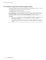
Page 269: ...ell com ps thirdpartylicenses Documentation feedback You can find the most up to date documents on the Honeywell Process Solutions support website at http www honeywellprocess com support If you have comments about Honeywell Process Solutions documentation send your feedback to hpsdocs honeywell com Use this email address to provide feedback or to report errors and omissions in the documentation F...

Page 270: ...t Center CCC To find your local CCC visit the website https www honeywellprocess com en US contact us customer support contacts Pages default aspx Training classes Honeywell holds technical training classes about Experion PKS These classes are taught by experts in the field of process control systems For more information about these classes contact your Honeywell representative or see http www aut...

Reviews: