43-TV-33-56 iss.4 GLO Aug 19 UK
16
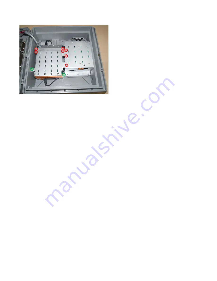
6. Make sure all the screws shown in red and green colours in Figure 28 are connected back.
7. Reconnect the CJCs, IO cabling and Power cable as required.
8. Close the door.
9. If the recorder has been removed from the panel, secure it back into the panel using the mounting brackets.
Copyrighted Materials. For more information please contact your supplier.
Figure 28
Reconnecting the IO
cards chassis


