background image

F118 IN-CEILING MEDIA AIR CLEANER

68-0209-2 Revised 11-07

6

5.

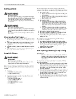
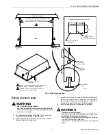
Standing on a secure platform, lift the cabinet body and 
insert it into the frame in the drop ceiling.

6.

Attach the free end of the wire to the structural ceiling.  
Align the cabinet edge with the upper side of the T-bars, 
without releasing the full weight onto the T-bars.

7.

Verify that the wire is strong enough to bear the load of 
the F118 before completing installation.

8.

Level the air cleaner.

Electrical Hookup

All wiring must comply with applicable codes and ordinances. 
The air cleaners are internally pre-wired.

IMPORTANT

Check that the air cleaner is grounded for proper 
operation and safety. 

Canadian Installations: Do not install in ceilings 
with thermal insulation value greater than R-40.

If installing an additional wall switch to regulate the air cleaner 
speed, only the Honeywell 32000234 (41105) Variable Speed 
Switch (optional) is recommended. Using a different speed 
controller can void the warranty. 

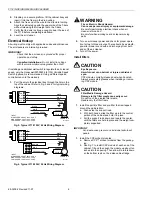
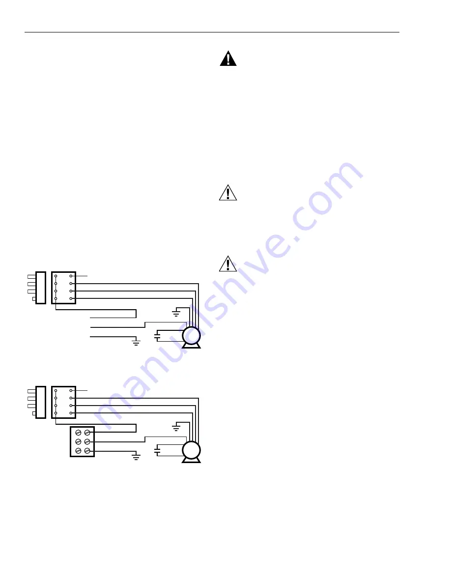
1.

Pull  the wire to the electrical box through the hole in the 
top of the cabinet. Refer to Fig. 5 and 6 for typical wiring 
diagrams.

Fig. 5. Typical F118 120V, 60 Hz Wiring Diagram.

Fig. 6. Typical F118 230V, 50 Hz Wiring Diagram.

WARNING

Fire or Electric Shock Hazard.
Can cause personal injury or equipment damage. 

Be careful performing electrical check when air 
cleaner is turned on.
Be careful when working near air cleaner moving 
parts.

2.

Turn on air cleaner power and check for proper opera-
tion for two to three minutes. There should be a smooth, 
powerful blower sound with air discharging from both 
ends of the air cleaner.

3.

Turn off the power.

Install Filters

CAUTION

Eye Exposure.
Harmful dust can obstruct or injure unshielded 
eyes.

CPZ module normally releases dust when handled.
Always wear safety glasses when installing or remov-
ing CPZ module.

CAUTION

Filter Media Damage Hazard.
Damage to the filter media can easily occur. 

Do not touch the pleated filter media.
Handle only the filter frame.

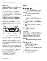
1.

Install the particle filter and pre-filter that is wrapped 
around the particle filter:
a. Push aside the support rods.
b. With both hands, slide the filter up into the central 

portion of the cabinet and hold it in place.

c. Pull the support rods down and toward the center, 

until the filters are held in place and the weight com-
pletely supported.

IMPORTANT

Avoid excessive pressure on individual adsorbent 
panels.

1.

Install the CPZ sorbent modules:
a. Remove CPZ™ sorbent modules from the packag-

ing.

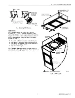
b. See Fig. 7 to install CPZ module at each end of the 

cabinet. Tilt and then push the module up about ten 
inches into the opening. Then allow it to rotate down 
so the bottom rests on the inside cabinet ledge.

ON

HI

MED

LO

1

2

3

4

BLACK
BLUE
RED

GREEN

ORANGE

YELLOW

BLACK

WHITE

GROUND GREEN

INPUT:
HIGH SPEED 2.8A AT 120V - 60 HZ
MED SPEED 2.0A AT 120V - 60 HZ
LOW SPEED 1.4A AT 120V - 60 HZ

FAN MOTOR

M16210A

ON

HI

MED

LO

1

2

3

4

BLACK
BLUE
RED

GREEN

ORANGE

YELLOW

BROWN

BLUE

GREEN/YELLOW

INPUT:
HIGH SPEED 2.8A AT 230V - 50 HZ
MED SPEED 2.0A AT 230V - 50 HZ
LOW SPEED 1.4A AT 230V - 50 HZ

FAN MOTOR

M14417

Summary of Contents for F118

Page 1: ...throughout the space This effect is the tendency of air to travel close to a wall contour when ejected from a jet The air cleaner draws contaminated air up from the center of the room forces it through the filters and then blows the filtered air out through the narrow ends of the air cleaner FEATURES The DOP particle filter is 95 percent efficient at 0 3 micron particles and more efficient on part...

Page 2: ... C to 66 C Operating Ambient temperatures usually below 77 F 25 C but occasionally as high as 104 F 40 C Humidity Up to 95 relative humidity non condensing Air Volume Electrical Ratings Grille Type Perforated metal Dimensions Fig 1 Approximate dimensions of F118 in in mm Mounting Hangs freely from structural ceiling Can be recessed into a drop ceiling frame Weight Shipping Cabinet and Contents 119...

Page 3: ...hang from a structural ceiling It mounts horizontally inside or outside of a drop ceiling system It also fits between joists set 24 in 610 mm on center When used with a drop ceiling system allow at least 12 in 305 mm clearance between the structural and drop ceiling to allow space for the air cleaner To ensure unobstructed airflow the grille which is one inch 25 mm deep must protrude below the dro...

Page 4: ...he spring loaded plungers at the other end of the cabinet c Set aside the grille 2 Remove the filters a Pre filter is wrapped around the particulate filter Two support rods in the center bay of the cabinet hold the particulate filter and the pre filter in place Push these rods apart and lift the filters out of the cabinet b Two CPZ sorbent modules wrapped in plastic are located at either end of th...

Page 5: ...wire a minimum of four times WARNING Equipment Falling Hazard Can cause personal injury structural weakening buckling or damage to equipment Be sure platform is stable and can support combined weight of installer and equipment Use assistant to help support equipment during instal lation DROP CEILING F118 BE SURE TO TWIST THE SUPPORT WIRE A MIINIMUM OF FOUR TIMES TO PROPERLY BEAR WEIGHT THERE MUST ...

Page 6: ... power and check for proper opera tion for two to three minutes There should be a smooth powerful blower sound with air discharging from both ends of the air cleaner 3 Turn off the power Install Filters CAUTION Eye Exposure Harmful dust can obstruct or injure unshielded eyes CPZ module normally releases dust when handled Always wear safety glasses when installing or remov ing CPZ module CAUTION Fi...

Page 7: ...pring loaded plungers and hardware at the opposite end of the cabinet 4 Close and latch the grille When installed and latched the grille protrudes about one inch below the surface of the drop ceiling Proper operation of the air cleaner requires that it be level Fig 8 Installing grille F118 CABINET TIP CPZ SORBENT FILTER MODULE SLIGHTLY TO INSERT INTO F118 CABINET M14418 SET CORNER OF FILTER MODULE...

Page 8: ... In a heavily contaminated area up to 15 air exchanges per hour can be necessary The factors that determine the rate of air exchange are Generation rates of the various pollutants Concentration level of the pollutants Desired contamination reduction level SERVICE WARNING Fire or Electric Shock Hazard Can cause personal injury or equipment damage Turn off power source before servicing air cleaner I...

Page 9: ...nt media life ranges from 12 to 18 months Change modules and filters more frequently in facilities that operate 24 hours a day NOTE When tobacco smoke is a contaminant both the par ticle filter and the CPZ adsorbent filter must be ser viced at the same time CAUTION Eye Exposure Harmful dust can obstruct or injure unshielded eyes CPZ modules normally release dust when handled Always wear safety gla...

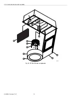
Page 10: ...F118 IN CEILING MEDIA AIR CLEANER 68 0209 2 Revised 11 07 10 Fig 10 F118 Air Cleaner components 1 3 2 4 M14421 5 8 9 7 6 ...

Page 11: ...F118 IN CEILING MEDIA AIR CLEANER 11 68 0209 2 Revised 11 07 NOTES ...

Page 12: ...NY LOSS OR DAMAGE OF ANY KIND INCLUDING ANY INCIDENTAL OR CONSEQUENTIAL DAMAGES RESULTING DIRECTLY OR INDIRECTLY FROM ANY BREACH OF WARRANTY EXPRESS OR IMPLIED OR ANY OTHER FAILURE OF THIS PROD UCT Some states do not allow the exclusion or limitation of incidental or consequential damages so this limitation may not apply to you THE WARRANTIES SET FORTH HEREIN ARE EXCLUSIVE AND AIR PURE SYTEMS EXPR...

Reviews: