background image

Addressable Fire Alarm Control Panel

ES-200X

ES-200XC

Manual

Document LS10131-000FL-E  Rev: C
7/25/2018   ECN:18-323

Summary of Contents for Fire-Lite Alarms ES-200X

Page 1: ...Addressable Fire Alarm Control Panel ES 200X ES 200XC Manual Document LS10131 000FL E Rev C 7 25 2018 ECN 18 323 ...

Page 2: ...t provide adequate warning of a fire Smoke detectors cannot be expected to provide adequate warning of fires caused by arson children playing with matches especially in bedrooms smoking in bed and violent explosions caused by escaping gas improper storage of flammable materials etc Heat detectors do not sense particles of combustion and alarm only when heat on their sensors increases at a predeter...

Page 3: ...inserting circuit boards Failure to do so can damage circuits Remove all electronic assemblies prior to any drilling filing reaming or punching of the enclosure When possible make all cable entries from the sides or rear Before making modifications verify that they will not interfere with battery transformer or printed circuit board location Do not tighten screw terminals more than 9 in lbs Over t...

Page 4: ...opriate version for a specific application Documentation Feedback Your feedback helps us keep our documentation up to date and accurate If you have any comments or suggestions about our online Help or printed manuals you can email us Please include the following information Product name and version number if applicable Printed manual or online Help Topic Title for online Help Page number for print...

Page 5: ...Fire Annunciators 19 ANN S PG Serial Parallel Interface Module 19 ANN I O LED Driver Module 20 ANN LED Annunciator Module 20 ANN RLY Annunciator Module 20 1 7 Getting Started 20 1 8 Telephone Requirements and Warnings 20 1 8 1 Telephone Circuitry 20 1 8 2 Telephone Company Rights and Warnings 21 1 8 3 For Canadian Applications 21 Section 2 Installation 22 2 1 Mounting the Backbox 22 2 2 Power 25 2...

Page 6: ...n 51 3 5 Programming and Passwords 51 3 6 Master Programming Level 52 3 6 1 Autoprogram 52 3 6 2 Point Program 53 Detector Programming 53 Module Programming 60 3 6 3 Zone Setup 68 Enable 68 Disable 68 Special Purpose Zone 69 Zones Installed 69 Zones Enabled 69 Zones Disabled 69 Zone Type 70 Zones Available 70 Zone Message 70 3 6 4 Loop Setup 71 Class 71 Loop Protocol 71 Device Addressing 71 3 6 5 ...

Page 7: ...4 5 Alarm Operation 108 4 6 CO Alarm Operation 109 4 7 Supervisory Operation 109 4 8 Process Monitor Operation 110 4 9 Hazard Tornado Condition Operation 110 4 10 Medical Alert Condition Operation 110 4 11 Mass Notification Operation 111 4 12 NAC Operation 111 4 13 Programmed Zone Operation 111 4 14 Disable Enable Operation 111 4 15 Waterflow Circuits Operation 111 4 16 Detector Functions 111 4 17...

Page 8: ...on 8 Firmware Upgrade 127 8 1 Firmware Upgrade 127 Section 9 Power Supply Calculations 128 9 1 Overview 128 9 2 Calculating the AC Branch Circuit 128 9 3 Calculating the System Current Load 128 9 3 1 Overview 128 9 3 2 How to Calculate System Current Load 128 9 4 Calculating the Battery Size 130 9 4 1 NFPA Battery Requirements 130 9 4 2 Selecting and Locating Batteries 130 Appendix A Software Zone...

Page 9: ... Contents Appendix G Central Station Points 152 Appendix H NFPA Requirements 154 Appendix I Open Short Ground Trip Values 155 Appendix J Canadian Applications 156 Index 159 Slide in Labels 163 ES 200X and ES 200XC Fire Alarm Control Panels Operating Instructions 165 ...

Page 10: ...nd Systems CAN ULC S527 99 Standard for Control Units for Fire Alarm Systems This Class A digital apparatus complies with Canadian ICES 003 Cet appareil numérique de la classe A est conforme à la norme NMB 003 du Canada Other Canadian Electrical Code Part I EIA 232E Serial Interface Standard EIA 485 Serial Interface Standard NEC Article 250 Grounding NEC Article 300 Wiring Methods NEC Article 760 ...

Page 11: ...y Trouble Input CAUTION HIGH VOLTAGE AC Power Supervised Nonpower Limited 120 or 240 VAC 50 60 Hz 3 25 amps Battery 24 VDC supervised nonpower limited 18 AH maximum USB Port J20 for firmware updates local programming using a personal computer and FS Tools utility or a thumb drive To disable ground fault detection slide SW1 to the left Important Disabling Ground Fault Detection voids UL NFPA Class ...

Page 12: ...onnector J15 es200annperi wmf ANN 80 LCD Text Annunciator Doc 52749 ANN I O LED Driver Doc 151416 ANN S PG Printer Driver Doc 151417 CHG 75 Charger Doc 51315 ANN R LED LED Display Doc 53032 ANN RLY Relay Card Doc 53033 4XTMF Reverse Polarity Module J12 J13 ANN Audio Control for ECC 50 100 Doc LS10001 000FL E IPOTS COM POTS and IP Communicator Doc LS10184 000GE E J6 CELL CAB FL GSM Communicator Doc...

Page 13: ...0 000 ft 3 000 m in LiteSpeed mode with twisted unshielded wire refer to Wire Requirements on page 143 Single addressable SLC loop which meets NFPA Class A Class B and or Class X requirements 198 addressable device capacity 99 detectors and 99 control relay monitor modules 99 software zones Four 4 Class B or four 4 Class A NAC Notification Appliance Circuits circuits special application power 3 0 ...

Page 14: ... batteries use the CHG 75 or CHG 120F Battery Charger and BB 55F Battery Box Minimum Battery Size 7 Amp Hour Note Refer to the programming section to disable the FACP battery charger when using an external battery charger Communication Loop TB12 24 VDC nominal 27 6 VDC maximum Maximum length refer to Wire Requirements on page 143 Maximum loop current is 400 mA short circuit or 100 mA normal Maximu...

Page 15: ...n resettable power Primary ANN BUS TB9 Class A or Class B wiring ANN BUS annunciator connector Terminal 1 A and Terminal 2 B Class A wiring uses Terminal 3 A Return and Terminal 4 B Return Annunciators require non resettable power The following figure illustrates the maximum current that is possible for each major panel output circuit and the total current available from the FACP TB5 TB6 TB7 TB8 5...

Page 16: ...scape key Two cursor keys left and right Menu Enter key Local Piezo Sounder A piezo sounder provides separate and distinct pulse rates for alarm trouble and supervisory conditions 1 4 Components Main Circuit Board The main circuit board contains the system s CPU power supply other primary components and wiring interface connectors The 4XTMF option module plugs in and is mounted to the main circuit...

Page 17: ... Manual for a list of compatible address able detectors 1 4 2 Intelligent Addressable Modules Control Modules and Monitor Modules provide an interface between the control panel and conventional notification and initiating devices Each module can be set to respond to an address with built in rotary switches The maximum address cannot exceed address 99 Note that a blinking LED on an addressable modu...

Page 18: ...the panel be enabled for remote download refer to FS Tools Upload Download on page 123 Remote interrogation of panel programming history logs detector status etc is possible without enabling the remote download option 1 6 2 Dress Panel An optional dress panel DP ES Ris available for the ES 200X required by ULC for Canadian installations The dress panel restricts access to the system wiring while a...

Page 19: ...0 LCD Annunciator FM and Canadian applications only ANN S PG Serial Parallel Printer Interface Module ANN I O LED Driver Module ANN LED Annunciator Module alarm trouble supervisory LEDs ANN RLED Annunciator Module red alarm LEDs only ANN RLY Relay Module can be mounted in the supplied FACP chassis When operating two ANN BUS circuits only one ANN S PG Printer module can be used in the system The pa...

Page 20: ...ty of devices which may be connected to the telephone line Excessive RENs on the telephone line may result in the devices not ringing in response to an incoming call In most but not all areas the sum of the RENs should not exceed five 5 0 To be certain of the number of devices that may be connected to the line as determined by the total RENs contact the telephone company to determine the maximum R...

Page 21: ...ommunications network protective operational and safety requirements as prescribed in the appropriate Terminal Equipment Technical Requirements document s The Department does not guarantee the equipment will operate to the users satisfaction Before installing this equipment users should ensure that it is permissible to be connected to the facilities of the local telecommunica tions company The equ...

Page 22: ...n page 23 2 Install center top fastener in the wall with the screw head protruding 3 Place backbox over the top screw level and secure 4 Mark and drill the left and right upper and lower mounting holes Note Outer holes closest to sidewall are used for 16 O C stud mounting 5 Install remaining fasteners and tighten 6 When the location is dry and free of construction dust install the chassis circuit ...

Page 23: ...igure 2 2 ES 200X Cabinet Mounting 9050udencl wmf Semi Flush Mounting Do not recess box more than 3 875 into wall to avoid covering venting holes on top of box Hinge Slot for optional Dress Panel Hinge Slot for optional Dress Panel Semi flush mounting hole Mounting slots for optional Trim Ring ...

Page 24: ... Installation Mounting the Backbox An optional Trim Ring P N TR CE is also available for semi flush mount installations 6 537 16 6cm 5 207 13 23cm 16 822 42 73 cm 19 26 48 92 cm Figure 2 3 Cabinet Dimensions Height Depth Width Left Side Right Side Top Bottom ...

Page 25: ... the panel s susceptibility to transients generated by lightning and electrostatic discharge Apply AC power to the panel only after the system is completely installed and visually checked Note that AC power must be applied to the panel before installing the battery interconnect cable refer to the following section 2 2 2 Battery Power The batteries must be sealed lead acid type Before connecting th...

Page 26: ...The NACs which are located on the main circuit board may be expanded via the FCPS Series field charger power supplies The following sections describe the configuration and wiring of Class B and Class A Notification Appliance Circuits on the ES 200X main circuit board PWR2 24V PWR1 Figure 2 5 Special Application Power Outputs 24 VDC Power limited Non resettable or Resettable Power 1 0 amperes max 2...

Page 27: ...rized Strobes Notification Appliance Circuit polarity shown in alarm state Dummy Load all unused circuit TB5 es200nacy wmf Polarized Strobes circuit number NAC 1 NAC 2 NAC 3 NAC 4 TB4 TB6 TB7 NAC4 NAC3 NAC2 NAC1 4 Class A Notification Appliance Circuits supervised and power limited Polarized Horns Polarized Horns Notification Appliance Circuit polarity shown in alarm state Polarized Bells Polarize...

Page 28: ... 200X to the sync input of the FCPS 24FS6 8 Power Sup ply The 24 VDC signal from TB8 follows that is mimics the signal on NAC1 This allows the devices connected to the power supply to be synchronized with the devices connected to NAC1 on the FACP The Remote Synchronization Output is power limited and supervised refer to UL Power limited Wiring Requirements on page 29 and can be wired in Class B or...

Page 29: ...ne installed closest to the backbox A typical wiring diagram for the ES 200X is shown below RTN OUT COMMUNICATOR DISPLAY 24V RTN OUT BATTERY N L2 EARTH H L1 USB A C NO NC C NO NC C NC NO SUPV TRBL ALRM ANN LC SLC RMT SYNC ANN BUS PRI ANN BUS SEC NAC4 NAC3 NAC2 NAC1 Figure 2 10 Typical UL Power limited Wiring Requirements Power limited Circuits Class 2 Power limited Circuits Class 2 AC Power Ground...

Page 30: ...ration necessary SW3 2 position dip switch Factory Settings Do not change unless instructed to do so by Honeywell Figure 2 11 Communicator Installation Customer Premises Equipment and Wiring Telephone Line FACP with IPOTS COM mounted internally Network Service Provider s Facilities Network Demarcation Point RJ31X Jack Unused RJ 11 Jack Unused RJ 11 Jack Telephone Telephone Telephone Answering Syst...

Page 31: ...dition to alarm and trouble reverse polarity A jumper option allows the reverse polarity circuit to open with a system trouble condition if no alarm condition exists A disable switch allows disabling of the transmitter output during testing to prevent accidental calling of the monitoring service Local Energy Municipal Box Service NFPA 72 Auxiliary Fire Alarm Systems Supervisory Current 5 0 mA Trip...

Page 32: ...TMF supervision in user programming Refer to 4XTMF Supervision on page 80 6 Reapply power to the FACP 7 For proper 4XTMF operation the output relays must be programmed for the factory default settings Alarm Relay 1 Trouble Relay 2 and Supervisory Relay 3 8 When the installation has been complete enable the 4XTMF module by sliding the disconnect switch to the left 9 Test system for proper operation...

Page 33: ... Standoff 4XTMF FACP main circuit board es2004xtmf wmf Jumper JS3 NOTE When a 4XTMF is installed enable supervision in panel programming Jumper JS3 on the FACP main circuit board can be used to configure the FACP supervisory relay for operation with the 4XTMF module Relay 3 at TB3 must be programmed as a supervisory relay Jumpering pins 2 3 on JS3 will allow the 4XTMF to generate a trouble if the ...

Page 34: ...arallel Printer Interface Module The total worst case current is calculated as follows Wiring Configuration Figure 2 17 illustrates the wiring between the FACP s Primary ANN BUS and ANN BUS devices Maximum Resistance Ohms 2 0 Volts Total Worst Case Current Draw amps Maximum Wire Length feet Maximum Resistance Ohms x 500 6 000 feet maximum Rpu where Rpu Ohms per 1 000 feet for various Wire Gauges s...

Page 35: ...ary Power Supply Figure 2 19 illustrates the powering of ANN BUS devices from an auxiliary power supply such as the FCPS 24FS6 8 when the total ANN BUS power requirements exceed the panel s DC Power Output capability TB1 4 3 2 1 Figure 2 18 Secondary ANN BUS wiring to ANN BUS Device ANN BUS Device ES 200X ANN BUS and power wiring are supervised and power limited 24 VDC nonresettable Secondary ANN ...

Page 36: ...ation Installation Ensure that all power AC and DC has been removed from the FACP before installing the annunciator Opening Closing Annunciator The following procedure details the steps used to open the annunciator in order to access the terminal block and DIP switches refer to figure below 1 Turn the key switch to the ON Unlocked position by turning the key counter clockwise 2 Push in the snap la...

Page 37: ...s can be used as a guide to wire the annunciator Make certain all power has been removed from the FACP prior to annunciator installation 1 Route wires from hole in backplate through wiring channel and then to ANN 80 terminal block TB1 2 Remove appropriate amount of wire insulation 3 Connect the wiring from the FACP ANN BUS to annunciator TB1 terminals 3 A 4 B Make certain to connect A to A and B t...

Page 38: ...te that the FACP will provide no indication of an ANN 80 trouble To clear the ANN 80 trouble condition enable the ANN BUS and program the address corresponding to the address set on the ANN 80 at the FACP ANN 100 Remote Fire Annunciator Specifications Operating Voltage 24 VDC Current Standby 20 mA Alarm 25 mA Ambient Temperature 32 F to 120 F 0 C to 49 C Max Wiring Distance from FACP 6 000 ft 1 80...

Page 39: ...e feature allows the programmer to quickly bring all installed ANN BUS modules online refer to Auto Configure on page 97 5 Connect a printer to the ANN S PG Parallel or Serial connectors refer to Figure 2 21 Only one printer can be connected Specifications Operating Voltage 24 VDC Current Alarm and Standby 45 mA Ambient Temperature 32 F to 120 F 0 C to 49 C Max Wiring Distance from FACP 6 000 ft 1...

Page 40: ...d DB 25 cable One end of the cable will plug into the DB 25 connector on the PRN printer and the other end plugs into the parallel connector on the ANN S PG module Note that the 9 pin DB 9 port on the ANN S PG is used to connect a serial printer The 25 pin port is used for a Centronics parallel printer cable Connect either a serial or parallel printer but not both at the same time Setting Printer ...

Page 41: ...ect ing LEDs and the DIP switch for selecting the ANN BUS ID number Specifications Max ANN BUS Voltage 24 VDC Max Current Alarm 200 mA Standby 35 mA Each LED 10 mA Operating Temperature 32 F to 120 F 0 C to 49 C For indoor use in a dry location only 1 10 11 20 21 30 31 40 LED Out LED Power not used LED Out LED Power not used LED Out LED Power not used LED Out LED Power not used ANN BUS ID Address ...

Page 42: ...Internal resistors are sized so that there is approximately 10 mA of current for each LED No series resistors are required LED outputs can be mapped to output circuits Refer to the programming section titled ANN I O Options on page 91 of this manual The LEDs are wired as illustrated in Figure 2 24 Note that the illustration depicts only connectors P1 and P2 Wiring is identical for P3 LEDs 21 30 an...

Page 43: ...nn ioleds2 wmf LED1 LED2 LED3 LED4 LED5 LED6 LED7 LED8 LED9 LED10 LED Power no connection Pin 1 2 3 4 5 6 7 8 9 10 11 12 LED11 LED12 LED13 LED14 LED15 LED16 LED17 LED18 LED19 LED20 LED Power no connection P1 P2 Pin 1 2 3 4 5 6 7 8 9 10 11 12 Cathode LEDs Anode Cathode LEDs Anode Figure 2 25 ANN LEDs shown in possible stacked configuration ann ledstacked wmf ...

Page 44: ...efer to the ANN LED Installation Document 53032 for more information ANN LED Board Layout and Connection to FACP Figure 2 27 illustrates the ANN LED board showing locations of screw terminals for connection to the FACP and the DIP switches for selecting the ANN BUS ID number Figure 2 26 Exploded View of ANN LED ann led wmf TB1 J1 SW1 JP2 ANN BUS 1 2 3 4 5 6 7 8 Figure 2 27 ANN LED Board Layout and...

Page 45: ...sis or inside the ROME Series enclosure Refer to the ANN RLY Installation Document 53033 for instructions on chassis mounting or to the ROME Series Installation Document 53530 for mounting in the separate backbox mounting holes mounting hooks through mounting slots grounding wire ANN RLY ANN MBRLY mounting bracket mounting holes mounting holes FACP Backbox Installation using ANN MBRLY mounting bra...

Page 46: ... ANN BUS Setup on page 90 for programming information Printer Configuration Refer to the documentation supplied with the printer for pertinent information about printer setup Set the printer s options as listed in the following table TB1 J1 SW1 JP2 ANN BUS 1 2 3 4 5 6 7 8 TB6 TB3 TB5 TB4 TB2 Figure 2 29 ANN RLY Board Layout and Connection to FACP ANN RLY Primary ANN BUS 24 VDC 24 VDC ANN BUS and p...

Page 47: ... detect the audio system connection during annunciator auto configuration No ANN Bus address selec tion is necessary at the FACP Once the FACP can communicate with the audio system FACP zones Z33 through Z56 become automatically dedicated as output zones for speaker circuits 1 through 24 respectively FACP zone Z32 is dedicated to turn on all speaker circuits FACP programming allows association bet...

Page 48: ...pter 3 of the ECC 50 100 Instruction Manual Doc LS10001 000FL E or Appendix D Programmed Activation by FACP in the ACC 25 50ZS Series Instruction Manual Doc 51889 Connect the ECC 50 100 panel s FACP Data Bus at TB13 to TB9 on the ES 200X FACP The only connection between the FACP and ACC 25 50ZS Series audio panel is a pair of communication wires connected between the A B terminals on TB9 of the FA...

Page 49: ...d Download on page 123 Remote Download Proprietary No Remote Download Proprietary Yes Remote Download Proprietary Yes for Proprietary system intended to protect only contiguous properties Control Module Delay N Refer to Control Module Delay on page 75 Control Module Delay 0 factory default no delay in Control Module activation Control Module Delay 1 180 delays control module activation from 1 180 ...

Page 50: ...ogramming utility can be downloaded from www firelite com for this purpose Local Programming and Editing Feature allows creation and editing of site specific custom programs using a Windows based computer and the FACP USB connection For programs requiring a large amount of data entry this method may be preferred The FS Tools programming utility can be downloaded from www firelite com for this purp...

Page 51: ...r up The following sections describe the initial programming procedures for a new system The same procedures are used to modify program ming in an existing system After completing the wiring of addressable devices to the SLC apply power to the control panel If the addressable devices have not yet been programmed into the FACP their LEDs will not flash and the following trouble message will be disp...

Page 52: ... prompts the control panel to poll all devices installed on the SLC loop The primary purpose of autoprogramming is to allow the installer a fast and easy way to bring the system on line as quickly as possible The first time the system is powered up it should be autoprogrammed If the system is already programmed and Autoprogram is initiated the system will only add default values for newly installe...

Page 53: ... display the following screen which allows the programmer to add a new detector address to programming A flashing cursor will appear in the position of the first asterisk to the left The programmer keys in the three digit detector address such as 005 The screen will then ask whether the detector being added is wireless Select 1 for wired detector or 2 for wireless detector When the choice is selec...

Page 54: ...owing will be displayed If the selected address has been added to programming device summary screens will be displayed These screens allow the programmer to view all device settings at a single glance Pressing the left or right arrow keys will allow the programmer to rapidly view the devices at the previous or next address if installed If a detector such as a photoelectric detector with the select...

Page 55: ...bled and will turn on the Trouble LED and Disable LED Type To select the type of detector being programmed press the 2 key while viewing the Edit Detector Screen 2 This will cause the control panel to display the following Detector Type Screens Pressing the down arrow key will display additional detector types as indicated in the following table Detector Type Action When Activated Smoke Photo Fire...

Page 56: ...tector 005 by assigning the same zone to it in this example Z001 Program an output such as a control module for PAS activation by assigning zone Z97 to it This control module may be connected to a signaling device used to indicate a PAS condition do not use a Notification Appliance Circuit for this purpose Enable zones Z001 and Special Purpose Zone PAS 97 and set the PAS delay timer to some value ...

Page 57: ...work If the detector is wireless the display reads Wireless Yes If the device is wired the display will read Wireless No Fore more information on the SWIFT wireless network refer to the SWIFT manual LS10036 000FL E Sounder Base The Sounder Base selection allows the programmer to enter different values if the selected detector is mounted in an addressable sounder base Pressing 2 while viewing Edit ...

Page 58: ... 6 will cause the following screen to be displayed Pressing 1 while viewing the Noun Adjective Screen will cause the following screen s to be displayed Note that the keyboard down arrow key must be pressed to see all the Adjective screens Press the number corresponding to the adjective that is to be used as a descriptor for the location of the detector currently being programmed When an adjective ...

Page 59: ...een 5 dis playing the new information at the bottom of the screen Recall Increment Function In addition the user may use the Recall Increment function at any time when the cursor is on the first letter of the Description Adjective or Noun field as follows If the zero key is pressed a 0 is placed in the first letter position If the zero key is then pressed a second time with no intervening key acti...

Page 60: ...or left arrow key which will return the display to the Add Module Screen 1 Delete Module Pressing 2 in the Modules Screen will display the Delete Module Screen which allows the programmer to delete a specific module A flashing cursor will appear in the position of the first asterisk to the left Using the panel keypad key in the module address such as 005 When the last digit is keyed in the followi...

Page 61: ...nes that the module is assigned to NNN the three digit zone number from 000 099 1M012 represents the Loop Device type and Device address 1 SLC Loop M Module and 012 Module Address 012 W or indicates whether or not the device is programmed for Walktest W programmed for walktest not programmed for walktest X or indicates whether or not the device is wireless X wireless wired If the selected address ...

Page 62: ...used Smoke Conventional Fire Alarm User Defined 5 same as previous Smoke Conventional Heat Conventional Fire Alarm User Defined 6 same as previous Heat Detector Medic Alert 1 General Purpose Signaling latching User Defined 7 same as previous Medic Alert Hazard Alert 1 General Purpose Signaling latching User Defined 8 same as previous Hazard Alert Tornado Alert 1 General Purpose Signaling latching ...

Page 63: ...oves to the next Z designation Continue entering zone assignments or the remaining zones can be left blank or programmed as general alarm zones Z000 When all desired changes have been made press the Enter key to store the zone assignments The display will return to the Edit Monitor Screen 4 Noun Adjective The Noun Adjective selection allows the programmer to enter specific descriptors about the mo...

Page 64: ...the right and repeat the process to enter the next character To enter a space press the QZ key four times until a blank appears in the desired position When all characters have been entered press the Enter key to store the information The display will return to the Edit Monitor Screen 4 dis playing the new information at the bottom of the screen Recall Increment Function In addition the user may u...

Page 65: ... S or Nonsilenceable W or represents Waterflow Timer Delay W Waterflow Timer Delay enabled Waterflow Timer Delay disabled ZNNN represents the first of five possible software zones that the module is assigned to NNN the three digit zone number from 000 099 1M002 represents the Loop Device type and Device address 1 SLC Loop M Module and 002 Module Address 02 To change the programming for the display...

Page 66: ...rogrammed device is Z000 for general alarm zone A flashing cursor will appear on the first 0 to the left Enter the three digit number corresponding to the zone that is to be assigned to this device The cursor moves to the next Z designation Continue entering zone assignments or the remaining zones can be left blank or programmed as general alarm zones Z000 When all desired changes have been made p...

Page 67: ... key to move the cursor one position to the right and repeat the process to enter the next character To enter a space press the QZ key four times until a blank appears in the desired position When all characters have been entered press the Enter key to store the information The display will return to the Edit Control Screen 4 dis playing the new information at the bottom of the screen Recall Incre...

Page 68: ...t to Silenceable No to enable the Delay Timer Wireless The Wireless selection will update automatically if the system recognizes a wireless device If the module is wireless the display reads Wireless Yes If the module is wired the display will read Wireless No 3 6 3 Zone Setup Pressing 3 while viewing Programming Screen 2 will access the Zone Setup screens as illustrated below Enable Pressing 1 fo...

Page 69: ...ress of the 3 key will cause the display to toggle between Two Stage 99 On and Two Stage 99 Off Refer to Two Stage Operation on page 77 for a description of this feature Pressing 1 while viewing the Special Purpose Zone Screen 2 will cause the display to change to Local Alm 96 On Each press of the 1 key will cause the display to toggle between Local Alm 96 On and Local Alm 96 Off When Zone 096 is ...

Page 70: ...RTANT In Zone Type Program Screen 1 selecting WATERFLOW will assign a Waterflow silenceable zone type to the selected zone Any signaling devices programmed to the same zone can be silenced by pressing the Alarm Silence key or by using the auto silence feature To program a waterflow circuit as nonsilenceable refer to System Setup on page 71 Zones Available Pressing 2 while viewing Zone Setup Screen...

Page 71: ...ows the user to rapidly enable disable various fire panel inputs and outputs during scheduled maintenance Banner This option allows the user to change the top two lines of the LCD display from the blank factory default readout to a user defined readout when the control panel is in Normal condition Time Date This feature allows the programmer to set the time display format 24 hr or 12 hr date and d...

Page 72: ...y will control Pressing 3 assigns all zones to the selected Function Key Each function key can be assigned to control any of the 4 onboard NAC circuits on the ES 200X By pressing the 2 key while viewing the Function Keys Screen 2 the following screen displays allowing the user to select the desired NAC circuit s Pressing 1 2 3 or 4 toggles the screen between Yes controlled by function key and No n...

Page 73: ...on to the right and repeat the process to enter the next character To enter a space press the 9 YZ key four times to place a blank in the desired position When all characters have been entered press the Enter key to store the information The display will return to the Banner Screen Time Date The control panel time and date can be changed by pressing 3 while viewing the System Setup Screen 1 The fo...

Page 74: ... the last week of the selected month Pressing 1 while viewing Daylight Savings Screen 2 will display another screen which allows the programmer to select the month that daylight savings time will end In this sub screen pressing 1 will select September 2 will select October and 3 will select November Pressing 2 while viewing Daylight Savings Screen 2 will display two sub screens which allow the pro...

Page 75: ...en which will indicate the new delay time AC Loss Delay The reporting of a loss of AC power to a central station can be delayed by programming the length of the desired delay The factory default setting is 2 hours Press 1 while viewing Timer Screen 2 to display the following Pressing 1 while viewing AC Loss Delay Screen 1 will program the FACP to transmit an AC Loss report immediately to the centr...

Page 76: ...table contains NAC type codes and their functions Silenceable Pressing 3 while viewing NAC Screen 1 will cause the display to change to Silenceable No This will prevent the selected main circuit board NAC from being silenced by pressing the Alarm Silence key or by the Auto Silence feature Each press of the 3 key will cause the display to toggle between Silenceable Yes and Silenceable No Important ...

Page 77: ...ing option the following sequence of events will occur during an alarm 1 The on board NACs which are programmed to General Alarm Zone 0 will activate with a 1st stage output upon activation of any alarm point 2 If the activated alarm point is directly mapped to a zone which is programmed to an on board NAC that NAC will go directly to 2nd stage coding output All other NACs not directly mapped to t...

Page 78: ...iance Circuit cannot exceed 2 5 amps Refer to the manufacturer s documentation sup plied with the Strobes to determine the maximum current draw for each strobe and ensure that the circuit maximum is not exceeded To ensure proper strobe and circuit operation there is also a limit to the number of strobes that can be attached to each circuit MNS Override The MNS Override feature when enabled allows ...

Page 79: ...available for Canadian applications The F1 function key is automatically configured to perform a manual alarm signal activation when pressed The F2 function key is automatically configured to perform a two stage bypass when pressed If NACs are set up for two stage operation the Silence Inhibit timer is automatically enabled and is fixed at 5 minutes AlarmNet supervision settings for Cellular and E...

Page 80: ...oggle between Trouble Rem 4 or Trouble Rem 24 Refer to the table on page 49 for permissible settings Language The language option is used to change the text on the panel display to either English or French Pressing the 3 key will cause the display to offer a choice of 1 English and 2 French Charger Enable If using an external battery charger the FACP battery charger must first be disabled Pressing...

Page 81: ...eturn to the History Screen 3 6 7 Communicator The communicator settings allow the user to configure the settings for the pre installed IPOTS COM and CELL MOD CELL CAB FL if installed in the system Pressing 2 while viewing the Programming Screen 3 will cause the following Communicator options to be displayed Communicator Installed The pre installed communicator provides communication to a central ...

Page 82: ... setting is Phone Line X supervised Supervision must be set to Yes if the selected transmission path is POTS Pressing 1 for Supervision while viewing the POTS Line X Screen 2 will change the screen to read Supervision No Each press of the 1 key will toggle the option between Supervise Yes and No Refer to the table on page 49 for permissible settings Gains The Gains value is the telephone s transmi...

Page 83: ...3 on the IP Set tings screen will display the following Enter the 4 digit PIN provided by AlarmNet and press Enter The display will indicate that it is sending the PIN to AlarmNet for verifica tion Ethernet Fault The Ethernet Fault Time is the duration of the communication loss between the FACP and the Ethernet infrastructure Pressing 1 on the IP Settings Screen 2 will display the following Select...

Page 84: ...nter the Central Station phone number that the Communicator will be contacting A maximum of 20 characters can be entered with valid entries being 0 9 and A C where A B and C 2 seconds pause A flashing cursor will appear in the lower left corner of the screen Enter the first digit then press the right arrow key to move the cursor to the right one position Enter the second digit and repeat the proce...

Page 85: ...dnight and 2359 11 59PM Ethernet To configure the communication method to contact central station as an Ethernet connection select 2 for Ethernet from the Comm Path Screen The following screens will display Enable To enable the Ethernet connection press 1 while viewing the Ethernet Options Screen 1 to change the display to Enabled Yes Each press of the 1 key will cause the display to toggle betwee...

Page 86: ...Path Refer to the table on page 49 for permissible settings The Supervision Interval is the time from the check in at AlarmNet to the FACP Select Dual Path when Ethernet and Cellular communications will be used Select Sole Path when only Ethernet or Cellular is used NFPA 2010 Dual Path Supervision Interval 24 Hours NFPA 2010 Sole Path Supervision Interval 5 min NFPA 2013 Dual Path Supervision Inte...

Page 87: ... the various Communication Formats The information shown in Table 3 3 is automatically programmed for the Central Station phone number Event Codes when the Ademco Contact ID or SIA Format is selected Enter 0s for an Event Code Setting to disable the report Disabled reports will not get called to the Central Station The programmer may enable the Event Types in programming as described on the previo...

Page 88: ...1 Zone Point FA FH MON USER DEF 5 111 Zone Point FA FH HEAT CONVENTIONAL 114 Zone Point KA KH MON USER DEF 6 114 Zone Point KA KH MEDIC ALERT 100 Zone Point MA MH MON USER DEF 7 100 Zone Point MA MH HAZARD ALERT 150 Zone Point PA PH MON USER DEF 8 150 Zone Point PA PH TORNADO ALRT 150 Zone Point PA PH MON USER DEF 9 150 Zone Point PA PH TAMPER 144 Zone Point TA TH MON USER DEF 11 144 Zone Point TA...

Page 89: ... A 00 00 ETHERNET FAULT 350 000 000 YS YK CELLULAR FAULT 350 000 000 YS YK PRINTER FAULT 336 000 000 VT VR NAC 1 FAULT 321 001 001 YA YR NAC 2 FAULT 322 002 002 YA YR NAC 3 FAULT 326 003 003 YA YR NAC 4 FAULT 327 004 004 YA YR 24 VDC FAULT 300 000 000 YP YQ VOICE EVAC FAULT 330 000 000 ET ER ACS FAULT 333 000 000 EM EN LCD 80F FAULT 330 000 000 EM EN PRI ANN BUS FAULT 333 000 000 ET ER SEC ANN BUS...

Page 90: ...the two programming screens are the addresses The Primary Bus module addresses will have a prefix of 1 while the Secondary Bus module addresses will have a prefix of 2 The following screen will be displayed for either bus circuit Pressing the down arrow key will allow the programmer to view additional screens displaying Addresses 1 8 To select one or more addresses for the installed module s press...

Page 91: ...or Zone information Pressing 1 while viewing ANN I O Address Screen 3 will select the Point or Zone range to be annunciated refer to the tables in ANN I O Zone Option on page 92 and ANN I O Point Option on page 93 Pressing 2 while viewing ANN I O Address Screen 3 will select either addressable detectors or addressable modules to be annunciated Module Type Screen 1 Module Type Screen 2 Module Type ...

Page 92: ...rger Fault Zone 037 Zone 077 9 NAC Fault Zone 038 Zone 078 10 Disabled Zone 039 Zone 079 11 Zone 000 Zone 040 Zone 080 12 Zone 001 Zone 041 Zone 081 13 Zone 002 Zone 042 Zone 082 14 Zone 003 Zone 043 Zone 083 15 Zone 004 Zone 044 Zone 084 16 Zone 005 Zone 045 Zone 085 17 Zone 006 Zone 046 Zone 086 18 Zone 007 Zone 047 Zone 087 19 Zone 008 Zone 048 Zone 088 20 Zone 009 Zone 049 Zone 089 21 Zone 010...

Page 93: ...036 Point 076 7 Battery Fault Point 037 Point 077 8 Charger Fault Point 038 Point 078 9 NAC Fault Point 039 Point 079 10 Disabled Point 040 Point 080 11 Point 001 Point 041 Point 081 12 Point 002 Point 042 Point 082 13 Point 003 Point 043 Point 083 14 Point 004 Point 044 Point 084 15 Point 005 Point 045 Point 085 16 Point 006 Point 046 Point 086 17 Point 007 Point 047 Point 087 18 Point 008 Point ...

Page 94: ...ollows The LED assignments for the modules annunciating Zone Ranges 060 089 and 090 099 will follow the same pattern as the second ANN RLED module Alarm Silenced NAC 1 Fault NAC 2 Fault NAC 3 Fault NAC 4 Fault Earth Fault Battery Fault Charger Fault Disabled Maintenance Zone 000 Active Alarm Zone 001 Active Alarm Zone 002 Active Alarm Zone 003 Active Alarm Zone 004 Active Alarm Zone 005 Active Ala...

Page 95: ...e Zone 004 Trouble Zone 000 Supervisory Zone 001 Supervisory Zone 002 Supervisory Zone 003 Supervisory Zone 004 Supervisory Zone 005 Active Alarm Zone 006 Active Alarm Zone 007 Active Alarm Zone 008 Active Alarm Zone 009 Active Alarm Zone 005 Trouble Zone 006 Trouble Zone 007 Trouble Zone 008 Trouble Zone 009 Trouble Zone 005 Supervisory Zone 006 Supervisory Zone 007 Supervisory Zone 008 Superviso...

Page 96: ...ve Alarm Point 064 Active Alarm Point 055 Active Alarm Point 056 Active Alarm Point 057 Active Alarm Point 058 Active Alarm Point 059 Active Alarm Point 060 Active Alarm Table 3 9 ANN RLED Module 2 Point Range 031 060 Alarm Silenced NAC 1 Fault NAC 2 Fault NAC 3 Fault NAC 4 Fault Earth Fault Battery Fault Charger Fault Disabled Maintenance Point 001 Active Alarm Point 002 Active Alarm Point 003 Ac...

Page 97: ...ules and automatically program the device type and address into the system For the Auto Configure to work the selected ANN BUS must be enabled the annunciators must be connected powered and a unique address must be set on each annunciator Pressing 3 while viewing ANN BUS X Screen 1 will begin the Auto Configure process and cause the following screen to be displayed Class A This option applies to t...

Page 98: ... 0 or 2 0 Stop Bits ANN LED Options This option allows the programmer to configure the optional ANN LED annunciator Pressing 2 while viewing the ANN BUS screen will display the following screens The Piezo Enable option allows the programmer to select whether the piezo sounder on any installed ANN LED module will ever sound Pressing 1 while viewing the ANN LED Options Screen causes the display to t...

Page 99: ...eature is unavailable The programming option will change to LMP BTN ENABLE in Canadian applications Pressing 2 while viewing the ANN 80 100 Options Screen 2 causes the display to toggle between Lmp Btn Enable Yes the ANN 100 will perform a local test of all LEDs and Lmp Btn Enable No The Drill Button Enable DRL BTN ENABLE option allows the programmer to select whether the Drill button on any insta...

Page 100: ... other circuits with no input or output correlations Pressing 3 while viewing Programming Screen 4 will cause the following screen to be displayed Pressing 1 while viewing the Program Check Screen will display an NAC screen similar to the following The example above indicates that NAC 1 has been programmed to Zones 25 31 44 55 and 67 but no input devices have been pro grammed to any of these zones...

Page 101: ...hown in the following screen 3 7 1 Disable Point Pressing 1 for Point Program while viewing Maintenance Screen 1 will cause the following screens to be displayed Select the device type by pressing 1 for an addressable detector or 2 for an addressable module The operator will be prompted to enter the three digit device address as shown in the following example for a detector A flashing cursor will ...

Page 102: ... to view the zones which have been programmed to the Notification Appliance Cir cuits on the control panel but have not been programmed to Initiating Devices as well as other circuits with no input or output correla tions Pressing 1 while viewing Program Check screen will cause a screen similar to the following to be displayed The example above indicates that NAC 1 has been programmed to Zones 025...

Page 103: ...play will change to indicate the latest event All stored events can be scrolled on the screen by pressing the up or down arrow keys To return to the first event press the 1st Event key Pressing 2 for View Points while viewing the Unit In Walktest screen will display one of the following screens If the system has no points installed the first screen will be displayed If points are installed the sec...

Page 104: ...o digit year The cursor will move one position to the right after each entry When the fourth digit of the year has been entered the display will return to the Time and Date Screen which will show the new date To enable the onboard battery charger press the 2 key while viewing System Screen 2 Each press of the key will toggle the screen between Charger Enab Yes and Charger Enab No The setting must ...

Page 105: ...een an output device connected to the control module can be used to indicate a PAS condition in the control panel Do not assign Zone 097 to a Notification Appliance Circuit when using this zone to indicate a PAS condition Pressing 2 will cause the display to change to Pre signal 98 On Each press of the 2 key will cause the display to toggle between Pre sig nal 98 On and Pre signal 98 Off When Zone...

Page 106: ...s a RESET IN SYSTEM message to be displayed on the LCD and sends the same message to the printer and history file It also per forms a lamp test by turning on all LEDs except the Ground LED piezo sounder and LCD display segments after the Reset key is released Any alarm or trouble that exists after a reset will resound the system 4 1 5 Function Keys F1 F4 The four function keys are user programmabl...

Page 107: ...ction of a trouble will cause the following The piezo to pulse 1 second On and 1 second Off The system Trouble LED to flash one second On and one second Off The trouble relay to activate TROUBL with device type noun adjective address and trouble description will appear on the LCD display The same message along with the time and date is sent to the optional printer and the history buffer Communicat...

Page 108: ...inter and history file If all troubles clear and there are no supervisory or fire conditions active in the system the system returns to normal mode operation and the System Normal message is shown on the LCD display and sent to the history and printer files The auto restore feature will restore cleared troubles even if the troubles were never acknowledged Note that pressing the Alarm Silence key w...

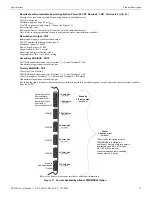
Page 109: ...ng a CO alarm condition Device type identifier in this example CAR MONOXIDE indicates a CO detector Second line in display ADJ refers to the user programmed adjective descriptor from library list resident in the control panel or custom entry via PC NOUN refers to the user programmed noun descriptor from library list resident in the control panel or custom entry via PC Third line in display Z002 in...

Page 110: ...ed to software zones 4 9 Hazard Tornado Condition Operation Hazard Tornado operation is intended for Manual activation Hazard Tornado Condition operation will initiate the following events The piezo sounder pulses 1 4 second On 1 4 second Off The LCD displays a hazard message along with the device name type address adjective noun associated zones and time date Communicate the hazard condition to t...

Page 111: ...ia coding 4 13 Programmed Zone Operation Each addressable detector and monitor module can be assigned to a maximum of five software alarm zones A general alarm zone Z000 may be listed for output control points but it is not necessary to list Z000 for input points since this is the default zone for all alarm input devices Zone Z000 is not activated by supervisory points When an input device alarms ...

Page 112: ...nitor module triggers an alarm the onboard piezo sounds immediately but the NACs are not activated for a user programmed time duration of up to three minutes Note that the alarm relay and communicator will respond to the initial alarm immediately In addition Zone 098 will activate This zone can be programmed to a control module which may be used to activate a sounder or indicator which the install...

Page 113: ...n alarm after the Alarm Silence key is pressed and every two minutes during a trouble condition after the Acknowledge Step or Alarm Silence key is pressed The beeps from the onboard piezo sounder will occur until the alarm or fault is cleared Note that if the trouble is not cleared within 24 hours the piezo will resound indicating that the trouble condition still exists 4 22 4 Waterflow Retard Tim...

Page 114: ...e reports this loss of power as an open condition in addition to the alarm condition Open Condition Addressable devices are monitored for fault conditions during Walktest mode When a new trouble condition occurs the FACP will acti vate all NACs and control modules programmed for Walktest and mapped to the faulty device then shut them off after eight seconds While in Walktest the trouble relay is a...

Page 115: ...able Disable Status Device Type Alarm Verification On Off for detectors Walktest Yes No PAS Positive Alarm Sequence Yes No for detectors only Pre Signal Yes No for detectors and monitor modules Zone Assignments five maximum Chamber Value Adjective Noun descriptor Silenceable Yes No for control modules MNS Override Enabled Disabled for control modules Wireless Yes No for detectors only Sounder Base...

Page 116: ...ptions for NAC 4 The resulting screens will display the following informa tion Enable Disable Status Circuit Type Bell Strobe etc Silenceable Nonsilenceable Auto Silence Enable Disable and time delay in minutes Coding Selection Temporal Steady etc Zone Assignments Silence Inhibit Enabled Disabled Synchronization Type System Sensor Wheelock or Gentex MNS Override Enabled Disabled MNS Active Yes No ...

Page 117: ...programmed for each device Pressing 3 for ANN BUS Options while viewing the Annunciator Screen allows the operator to view the settings for any ANN S PG ANN LED ANN 80 and ANN 100 installed in the system Pressing 1 for ANN S PG Options while viewing ANN BUS Screen 2 will display the options selected for the installed ANN S PG annunciators Pressing 2 for ANN LED Options while viewing ANN BUS Screen...

Page 118: ...rovides information on the receiver such as CS account info Pressing 3 for Cellular indicates whether the receiver has been enabled or disabled It also provides information on the receiver such as the CS account Communicator Screen 3 allows the user to view the Event Codes for the chosen communication format as well as the Test Time Interval and 24 Hour Test Time Communicator Screen 4 allows the u...

Page 119: ...ds Allows a smoke detector to retain its original ability to detect actual smoke and resist false alarms even as dirt and dust accumulate Reduces maintenance requirements by allowing the control panel to automatically perform the periodic sensitivity measurements required by NFPA Standard 72 The FACP software also provides filters to remove transient noise signals usually caused by electrical inte...

Page 120: ...the following screens 4 24 13 Battery Charger Read Status Screen 6 indicates whether the onboard battery charger is enabled or disabled 4 24 14 4XTM Supervision Read Status Screen 6 indicates whether 4XTMF Supervision is enabled or disabled 4 24 15 Remote Sync Read Status Screen 6 indicates whether remote synchronization is enabled or disabled Figure 4 1 Diagram of Maintenance Levels DIRTY Accepta...

Page 121: ...ine Two phone numbers must be programmed the primary Central Station phone number and the secondary Central Station phone number All system reports will be transmitted to the primary Central Station phone number Reports will automatically be sent to the secondary Central Station phone number if attempts to transmits to the primary Central Station phone number are unsuccessful If 10 total attempts ...

Page 122: ...01 01 03 7 With software V1 86 8 With software V1 72 9 With DSP4016 and V1 6 Line Card 10 With software V3 9 IMPORTANT It is the installer s responsibility to ensure that the Digital Alarm Communicator Transmitter is compatible with the Central Station Receiver utilized by the monitoring service prior to installation The Compatibility Table provides a list of compatible receivers and associated so...

Page 123: ... etary setting The FS Tools Download option can be selected from the main menu screen as shown below Pressing 3 for FS Tools Up Download while viewing the main menu will cause the following screen to be displayed The FS Tools Download password default 22222222 must be entered to access the FS Tools Download feature Note that the default password can be changed using the Password Change option refe...

Page 124: ...e viewed or changed by anyone other than a master user Viewing of the secret code is pro hibited at the control panel Prior to allowing an upload or download of data the control panel will verify the secret code transmitted by the Service Terminal Time out at Control Panel Upon answering an incoming call on the primary Central Station phone line the control panel will listen for a modem connection...

Page 125: ...ard The USB Download option can be selected from the main menu screen as shown below Pressing 4 for Local Up Download while viewing the main menu will cause the following screen to be displayed The Local Upload Download password default 22222222 must be entered to access the Local Upload Download feature Note that the default password can be changed using the Password Change option refer to Passwo...

Page 126: ...disable any further downloads to a flash drive Also following 30 minutes of inactivity including up downloading the Accept Download screen will time out causing the display to return to the System Normal screen Important The program database created by the FS Tools programming utility will be called FS_200 cfg on the USB flash drive Before loading the new database into the fire panel the existing ...

Page 127: ...he following screen to be displayed Before upgrading any software the panel will give the option to save current programming to a flash drive Press 1 for No to bypass pro gramming backup or press 2 for Yes to save a copy of the current programming to the flash drive The USB thumb drive must be in FAT32 file system format This is typically the default format An error message will display if there i...

Page 128: ...e primary AC power is applied The continuous sys tem current load is highest during a fire alarm condition To calculate the fire alarm load on the internal power supply use Calculation Column 1 in Table 9 3 on page 129 The secondary power source batteries must be able to power the system under both standby and fire alarm conditions upon loss of pri mary AC power To calculate the fire alarm load on...

Page 129: ...6 X 0 00200 BG 12LX X 0 00030 CMF 300 X 0 00039 CMF 300 6 X 0 00225 CRF 300 X 0 00027 CRF 300 6 X 0 00145 I300 X 0 00040 ISO 6 X 0 00045 W GATE X 0 040 or 0 024 6 NAC 17 X X NAC 27 X X NAC 37 X X NAC 47 X X FCPS remote sync X 0 02 X 0 0217 Current Draw from TB3 Sum each column for totals AC Powered Fire Alarm Load 8 Battery Powered Fire Alarm Load 9 Battery Powered Standby Load 10 Table 9 3 System...

Page 130: ...PA Battery Requirements NFPA 72 Local Proprietary Central Auxiliary and Remote Fire Alarm Systems require 24 hours of standby power followed by 5 min utes in alarm 9 4 2 Selecting and Locating Batteries Select sealed lead acid batteries that meet or exceed the total ampere hours calculated in Table 9 4 The control panel can charge batter ies in the 7 AH to 18 AH range The control panel cabinet is ...

Page 131: ... 99 addressable input devices assigned to it and from 1 to 99 addressable output devices assigned to it Monitor and control modules comprise one group of 99 addresses with each module having a unique address from 1 to 99 Detectors comprise a separate group of 99 addresses each detector having a unique address from 1 to 99 in its group Be careful not to duplicate addresses within any one group modu...

Page 132: ...tion of Input and Output Zones Input Devices Zones Output Devices ZONE 01 ZONE 02 ZONE 03 smoke 01 smoke 02 monitor 01 monitor 02 monitor 03 smoke 03 smoke 04 smoke 05 smoke 06 smoke 07 monitor 04 control 06 control 05 control 07 control 09 control 08 control 10 control 11 control 12 control 13 ...

Page 133: ...Type Zone Number ADJ NOUN 01 smoke 1 FIRST HALL 51 02 smoke 1 ELEV LOBBY 52 03 smoke 2 2ND FLOOR 53 04 smoke 2 ROOM 210 54 05 smoke 3 3RD FLOOR 55 06 smoke 3 MEZZANINE 56 07 smoke 3 MECH ROOM 57 08 58 09 59 10 60 11 61 12 62 13 63 14 64 15 65 16 66 17 67 18 68 19 69 20 70 21 71 22 72 23 73 24 74 25 75 26 76 27 77 28 78 29 79 30 80 31 81 32 82 33 83 34 84 35 85 36 86 37 87 38 88 39 89 40 90 41 91 4...

Page 134: ...monitor 1 2 52 03 monitor 1 2 53 04 monitor 3 54 05 control 1 55 06 control 1 56 07 control 1 57 08 control 2 58 09 control 1 2 3 59 10 control 2 60 11 61 12 62 13 63 14 64 15 65 16 66 17 67 18 68 19 69 20 70 21 71 22 72 23 73 24 74 25 75 26 76 27 77 28 78 29 79 30 80 31 81 32 82 33 83 34 84 35 85 36 86 37 87 38 88 39 89 40 90 41 91 42 92 43 93 44 94 45 95 46 96 47 97 48 98 49 99 50 Table A 2 Modu...

Page 135: ...e Type Zone Number ADJ NOUN 01 51 02 52 03 53 04 54 05 55 06 56 07 57 08 58 09 59 10 60 11 61 12 62 13 63 14 64 15 65 16 66 17 67 18 68 19 69 20 70 21 71 22 72 23 73 24 74 25 75 26 76 27 77 28 78 29 79 30 80 31 81 32 82 33 83 34 84 35 85 36 86 37 87 38 88 39 89 40 90 41 91 42 92 43 93 44 94 45 95 46 96 47 97 48 98 49 99 50 Table A 3 Blank Detector Programming Sheet ...

Page 136: ...ss Device Type Zone Number ADJ NOUN 01 51 02 52 03 53 04 54 05 55 06 56 07 57 08 58 09 59 10 60 11 61 12 62 13 63 14 64 15 65 16 66 17 67 18 68 19 69 20 70 21 71 22 72 23 73 24 74 25 75 26 76 27 77 28 78 29 79 30 80 31 81 32 82 33 83 34 84 35 85 36 86 37 87 38 88 39 89 40 90 41 91 42 92 43 93 44 94 45 95 46 96 47 97 48 98 49 99 50 Table A 4 Blank Module Programming Sheet ...

Page 137: ...ES 200X Series Manual P N LS10131 000FL E C 7 25 2018 137 Notes ...

Page 138: ...r Loop Protocol LITESPEED Secondary Phone Number Trouble Reminder 24 Hr Primary Comm Format Ademco Contact ID Banner Secondary Comm Format Ademco Contact ID Time Format 12 Hr ANN Primary Enabled No Hours Setting 12 ANN Primary Modules Addr 1 8 None Minutes Setting 00 ANN Secondary Enabled No Second Settings 00 ANN Secondary Modules Addr 1 8 None AM PM Setting AM ANN S PG Port Serial Month Setting ...

Page 139: ... Transmitter Module for connection to the RS82 Remote Station Receiver See Figure C 2 Remote Station Connection Using 4XTMF Module on page 140 for installation instructions for this unit NFPA 72 Auxiliary Fire Alarm System 4XTMF Transmitter Module for connection to a compatible listed Local Energy Municipal Box This unit must be installed as illustrated in the section titled 4XTMF Transmitter Modu...

Page 140: ...nstallation on page 31 for detailed information RS82 Remote Station Receiver UL listed Refer to Instruction Manual for Remote Station Receiver Model RS82 Polarity Shown is Normal Standby 4XTMF Transmitter Module Cutting TBL Jumper allows the reverse polarity circuit to open with a system trouble condition if no alarm condition exists Power limited Figure C 2 Remote Station Connection Using 4XTMF M...

Page 141: ...ch will automatically activate on any Trouble condition Form C Alarm contact programmed to activate on General Alarm ES 200X Main Board ES 200X Addressable Fire Control Panel Notes 1 Connection between the ES 200X and the transmitter are supervised by the transmitter 2 This ES 200X Transmitter arrangement can be employed for NFPA 72 Proprietary Protective Signaling System 3 Potter Electric Model E...

Page 142: ...BL ALRM SLC PWR1 RMT SYNC ANN BUS PRI ANN BUS SEC NAC4 NAC3 NAC2 NAC1 FACP Main Circuit Board CMF 300 Control Module 24 VDC Nonresettable SLC Loop B B red black MBT 1 brown wire white wire EOLR 1 Power Supervision Relay Alarm polarity shown To next device on SLC Loop The addressable Control Module must be programmed as Silenceable and General Alarm Gamewell Model M34 56 Local Energy Municipal Box ...

Page 143: ...m 12 AWG 3 25 mm2 Genesis 4410 Signal 98230 Belden 9583 WPW999 14 AWG 2 00 mm2 Genesis 4408 4608 Signal 98430 Belden 9581 WPW995 16 AWG 1 30 mm2 Genesis 4406 4606 Signal 98630 Belden 9575 WPW991 Direct Burial Cable Isotec NP713110VNQ S 18 AWG 0 75 mm2 Genesis 4402 4602 Signal 98300 Belden 9574 WPW975 Direct Burial Cable Isotec NP714110VNQ S LITESPEED MODE Twisted unshielded pair 40 ohms maximum pe...

Page 144: ...tex brand notification appliances the UL Max current rating published in their data sheets must be used in order to maintain performance under low battery conditions with the maximum wire resistances shown in the table above NAC Load Amps Max allowable total loop resistance ohms CLASS B Max allowable wire pair length feet CLASS A Max allowable wire pair length feet AWG 12 solid AWG 14 solid AWG 16...

Page 145: ...The monitor module s display label must be programmed to display HVAC SHUTDOWN When a shutdown event occurs the control module will both shut down the fans and activate the monitor module When the control module is active the monitor module will indicate a trouble condition at the FACP along with the label HVAC SHUTDOWN If using a NAC control module for HVAC shutdown monitor the state of the contr...

Page 146: ...ogram the HVAC OVRRIDE type code to the monitor module which will be used to override the HVAC SHUTDN control module and prevent the fans from turning off refer to Type Monitor under the section titled Edit Module Screen for Monitor Module on page 60 The HVAC OVRRIDE monitor module does not latch when activated Activating a switch connected to the monitor module will over ride all HVAC SHUTDN cont...

Page 147: ...1 for point address 1 up to 99 for point address 99 F 2 Ademco Contact ID Typical Printout A typical printout from a Central Station receiver such as the Ademco 685 of alarm and trouble reports in the Ademco Contact ID Reporting Structure follows Notes 1 11 is an example of a Receiver Line Card showing which receiver and line card the message was transmitted to 2 Q which is the Event Qualifier for...

Page 148: ... PANIC Audible Panic Burglar Alarms 130 130 Burglary BURG Burglary 131 Perimeter BURG Perimeter 132 Interior BURG Interior 133 24 Hour BURG 24 Hour 134 Entry Exit BURG Entry Exit 135 Day Night BURG Day Night 136 Outdoor BURG Outdoor 137 Tamper BURG Tamper General Alarms 140 140 General Alarm ALARM General Alarm 141 Polling loop open ALARM Polling Loop Open 142 Polling loop short ALARM Polling Loop...

Page 149: ...E System Low Battery 303 RAM checksum bad TROUBLE RAM Checksum restore not applicable 304 ROM checksum bad TROUBLE ROM Checksum restore not applicable 305 System reset TROUBLE System Reset restore not applicable 306 Panel program changed TROUBLE Prog Change restore not applicable 307 Self test failure TROUBLE Self Test Failure 308 System shutdown TROUBLE System Shutdown 309 Battery test failure TR...

Page 150: ...ENING Group User CLOSING Group User 403 Automatic Open Close OPENING Automatic CLOSING Automatic 404 Late Open Close OPENING Late CLOSING Late 405 Deferred Open Close Opening not used Closing not used 406 Cancel OPENING Cancel CLOSING Cancel 407 Remote arm disarm OPENING Remote CLOSING Remote 408 Quick arm Opening not applicable CLOSING Quick Arm 409 Keyswitch Open Close OPENING Keyswitch CLOSING ...

Page 151: ...s 572 24 Hour zone bypass BYPASS 24 Hour Bypass 573 Burglar bypass BYPASS Burg Bypass 574 Group bypass BYPASS Group Bypass Test Misc 600 601 Manual trigger test TEST Manually Triggered restore not applicable 602 Periodic test report TEST Periodic restore not applicable 603 Periodic RF transmission TEST Periodic Radio restore not applicable 604 Fire test TEST Fire Test restore not used 605 Status r...

Page 152: ...7 067 099 099 004 004 036 036 068 068 100 not used 005 005 037 037 069 069 006 006 038 038 070 070 007 007 039 039 071 071 008 008 040 040 072 072 009 009 041 041 073 073 010 010 042 042 074 074 011 011 043 043 075 075 012 012 044 044 076 076 013 013 045 045 077 077 014 014 046 046 078 078 015 015 047 047 079 079 016 016 048 048 080 080 017 017 049 049 081 081 018 018 050 050 082 082 through 019 0...

Page 153: ... 009 200 041 232 073 169 010 201 042 233 074 170 011 202 043 234 075 171 012 203 044 235 076 172 013 204 045 236 077 173 014 205 046 237 078 174 015 206 047 238 079 175 016 207 048 239 080 176 017 208 049 240 081 177 018 209 050 241 082 178 019 210 051 242 083 179 020 211 052 243 084 180 021 212 053 244 085 181 022 213 054 245 086 182 023 214 055 246 087 183 024 215 056 247 088 184 025 216 057 248...

Page 154: ...cy ES 200X Y Y Y Y Y Y ES 200XC Y Y Y Y Y Y IPOTS COM pre installed communicator Y 4XTMF O Y O 2 2 One of the indicated modules is required when the IPOTS COM is not employed O O 2 O DP ES R O O O O O O BB 55F 3 3 Listed separately O O O O O O ANN LED 3 O O O O O Y ANN 80 3 O O O O O Y ANN 100 3 O O O O O Y ANN S PG 3 O O O O O Y ANN I O 3 O O O O O Y ANN RLED 3 O O O O O Y ANN RLY 3 O O O O O Y W...

Page 155: ...trip values and restoral values for the NAC circuits on the FACP Output Circuit Terminal Trip Resistance in ohms Remote Sync 360K Remote Sync 330K NAC 1 2 360K NAC 1 2 320K ANN Bus A 270K ANN Bus B 265K Aux Power 370K Aux Power 320K SLC 125K SLC 320K Table I 1 Earth Fault Trip Values Circuit Trip Resistance in ohms Restore Value NAC 1 2 Shorts below 1 75K 2K NAC 1 2 Opens above 25K 23K Table I 2 N...

Page 156: ...l alarm signal activation when pressed The F2 function key is automatically configured to perform a two stage bypass when pressed which advances NAC coding directly to the second stage alarm The F3 function key is automatically configured to perform an automatic alarm signal cancel in two stage NAC operation This prevents the NAC from advancing to the second stage alarm If NACs are set up for two ...

Page 157: ...ACP Maximum Configuration Eight ANN LEDs ANN LEDs FACP ANN LED ANN I O ANN S PG ANN RLY 9200ulsc annled8 wmf optional ECC 50 100 audio system When using an audio system 7 ANN LEDs can be used Secondary ANN BUS data on connector TB10 power on TB11 Terminals 5 6 with power programmed as non resettable Primary ANN BUS data on connector TB9 non resettable power on TB11 Terminals 1 2 in metal conduit a...

Page 158: ...and the MMF 300 must be mapped to the same zone which is programmed for supervisory operation 2 No other device can be mapped to that supervisory zone 3 Wire gauge must be 18AWG minimum red black violet violet 47KΩ resistor TB12 SLC Loop Output Figure J 3 Alternate Transmission for Supervisory Signals revpol wmf T10 Comm2 T9 N C 2 T8 N O 2 T7 Comm1 T6 N C 1 T1 SLC T2 SLC T5 N O 1 If the SLC device...

Page 159: ...ection 25 charger capacity 14 see also secondary power 14 25 battery box 18 BB 26 17 battery charger 19 disable 14 72 enable 104 external 19 BB 26 17 BB 55F see also battery box 17 18 C cabinet dimensions 23 24 cabinet mounting 22 calculate system current draw 128 calculating the battery size 130 Canadian applications 21 156 Canadian option 71 79 156 CELL CAB FL 31 CELL MOD 31 cellular supervision...

Page 160: ...ator 31 guidelines ANN Bus annunciators 19 H hazard condition 110 history 81 erase 81 maintenance level 102 view events 81 history file 13 HVAC control 145 HVAC OVRRIDE 146 HVAC RESTART 146 HVAC SHUTDN 145 I indicators 16 installation 22 intelligent 13 invalid password 99 inventory 13 INVREP 119 IP settings 83 K key panel 16 function keys 16 service program keys 16 keyboard and keypad 49 L lamp te...

Page 161: ...14 power supply calculations 128 power limited relay connections 26 power up first time 51 preferred DNS 83 pre signal 13 56 69 function 112 selection 63 pre signal delay timer 74 75 primary ANN BUS 156 primary ANN Bus 15 90 primary communication path 84 primary phone number 84 primary power see also AC Power 25 printer configuration 46 connection 46 setup 46 printer connection 39 printer module 1...

Page 162: ...lephone circuitry 20 telephone line 30 telephone line supervision 82 telephone settings 82 84 test time interval 85 time and date maintenance level 104 time date setting 71 73 time out 124 timers 71 transmittal priorities 121 transmitter module 31 see also 4XTMF module 14 18 trouble 107 trouble display 107 trouble relay 13 trouble reminder 71 113 116 trouble responses 108 two stage operation 69 77...

Page 163: ...nter of the keypad next to the Function Keys slide each label into the groove towards the outer edge Function Keys F1 and F3 are not programmable in Canadian applications Those keys must use the pre printed labels below Figure 1 1 Slide in Labels ALARM SIGNAL ACTIVATION ALARM SYSTEM CANCEL ACTIVATION DU SIGNAL D ALARME TWO STAGE BYPASS DÉROGATION EN DEUX ÉTAPES Figure 1 2 Slide in Labels for Canad...

Page 164: ...164 ES 200X Series Manual P N LS10131 000FL E C 7 25 2018 ...

Page 165: ...will prevent silencing of NACs for five minutes after an alarm see manual To test the indicators LCD display and piezo Press and release the RESET button and check all indicators LEDs Every indicator LED should be on LCD shows all pixels on piezo sounder beeps For more information refer to the ES 200X Series Manual Document LS10131 000FL E It is kept in the following location _____________________...

Page 166: ...Cut along dotted line ...

Page 167: ...LIED WITH RESPECT TO THE PRODUCTS TRADEMARKS PROGRAMS AND SERVICES RENDERED BY MANUFACTURER INCLUDING WITHOUT LIMITATION INFRINGEMENT TITLE MERCHANTABILITY OR FITNESS FOR ANY PARTICULAR PURPOSE MANUFACTURER SHALL NOT BE LIABLE FOR ANY PERSONAL INJURY OR DEATH WHICH MAY ARISE IN THE COURSE OF OR AS A RESULT OF PERSONAL COMMERCIAL OR INDUSTRIAL USES OF ITS PRODUCTS This document constitutes the only...

Page 168: ...One Fire Lite Place Northford CT 06472 1601 USA USA Phone 203 484 7161 Canada Phone 905 856 8733 www firelite com ...

Reviews: