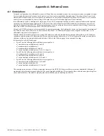
ES-200X Series Manual —
P/N LS10131-000FL-E:C 7/25/2018
119
Read Status
Operating Instructions
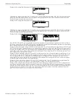
Pressing
1
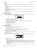
while viewing Print Screen #2 allows the user to print the detector data for each addressable smoke detector connected to the
system. A printout, similar to the following example, will be generated if an optional printer is connected to the FACP.
Chamber Value
The Chamber value should be within the indicated range for the following smoke detectors:
•
SD355CO, SD355(T/R), SD350(T), SD365(T/R), D350(R), and SD300(T) Addressable Photoelectric Smoke Detectors:
405 - 2100
(obscuration of 1.00%/ft to 3.66%/ft.)
•
CP355, CP350, and CP300 Addressable Ionization Smoke Detectors:
750 - 2100
(obscuration of 0.50%/ft. to 1.44%/ft.)
If the addressable smoke detector’s Chamber reading is not within the acceptable range, clean the detector and check the Chamber value
again. If the reading is still not within the acceptable range, immediately replace the detector.
Drift Compensation
Drift compensation uses software algorithms that identify and compensate for long-term changes in the data readings from each address-
able smoke detector. These long-term changes in detector data readings are typically caused by dirt and dust accumulation inside the
smoke chamber. Drift compensation performs the following functions:
•
Samples photoelectric smoke detectors every 6 seconds and ionization smoke detectors every 3 seconds
•
Allows a smoke detector to retain its original ability to detect actual smoke and resist false alarms, even as dirt and dust accumulate
•
Reduces maintenance requirements by allowing the control panel to automatically perform the periodic sensitivity measurements
required by NFPA Standard 72
The FACP software also provides filters to remove transient noise signals, usually caused by electrical interference.
Maintenance Alert
The software determines when the drift compensation for a detector reaches an unacceptable level that can compromise detector perfor-
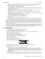
mance. When a detector reaches an unacceptable level, the control panel indicates a maintenance alert. Table 4.1 summarizes the three
levels of maintenance alert:
DEVICE #
DEVICE TYPE
% DRIFT COMP
CHAMBER
TIME/DATE
1D001
SMOKE (PHOTO)
20
1281
12:01 AM 01-08-2016
1D002
SMOKE (PHOTO)
20
1281
12:01 AM 01-08-2016
1D003
SMOKE (PHOTO)
21
1259
12:01 AM 01-08-2016
1D004
SMOKE (PHOTO)
20
1309
12:02 AM 01-08-2016
1D005
SMOKE (PHOTO)
21
1281
12:02 AM 01-08-2016
1D006
SMOKE (PHOTO)
20
1322
12:02 AM 01-08-2016
1D007
SMOKE (PHOTO)
20
1280
12:02 AM 01-08-2016
1D008
SMOKE (PHOTO)
20
1215
12:02 AM 01-08-2016
1D009
SMOKE (PHOTO)
20
1310
12:02 AM 01-08-2016
Maintenance Level:
FACP Status Displays:
Indicates:
Low Chamber Value
INVREP
A hardware problem in the detector
Maintenance Alert
DIRTY1
Dust accumulation that is near but below the allowed
limit.
DIRTY 1
indicates the need for maintenance
before the performance of the detector is
compromised
Maintenance Urgent
DIRTY2
Dust accumulation above the allowed limit.
Table 4.1 Maintenance Alert Levels

