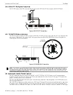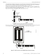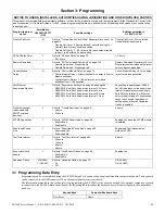
ES-200X Series Manual —
P/N LS10131-000FL-E:C 7/25/2018
55
Master Programming Level
Programming
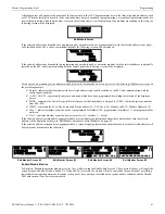
Normal - indicates that the detector with the selected address is physically installed on the SLC and communicating with the
control panel (enabled)
<ADJ><NOUN> - represents the adjective and noun, which have been programmed, describing the location of the displayed
device
ZNNN - represents the first of five possible software zones that the detector is assigned to (NNN = the three digit zone number
from 000 - 099)
V or * - indicates whether or not alarm verification is enabled (V = alarm verification enabled and * = alarm verification
disabled)
W or * - indicates whether or not walktest is enabled (W = walktest enabled and * = walktest disabled)
X or * - indicates whether or not the detector is wireless (X = wireless detector and * = wired detector)
1D017 - represents the Loop, Device type and Device address (1=SLC Loop, D=Detector and 017=Detector Address 017)
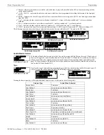
The following examples show the editing of a photoelectric smoke detector with address 017, located on the SLC loop:
Enable/Disable Detector
To Enable or Disable the detector, press the
1
key while viewing the Edit Detector Screen #2. Each press of
the key will toggle the screen between
Enabled Yes
and
Enabled No
. If
Enabled No
is selected, the detector
will not be polled by the control panel, preventing the detector from reporting alarms and troubles to the
panel. The control panel will display the device type and address which has been disabled and will turn on
the Trouble LED and Disable LED.
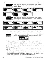
Type
To select the type of detector being programmed, press the
2
key while viewing the Edit Detector Screen #2.
This will cause the control panel to display the following Detector Type Screens:
Pressing the down arrow key will display additional detector types as indicated in the following table.
Detector Type
Action When Activated
Smoke Photo
Fire Alarm
User-Defined-1
same as previous (Smoke Photo)
Smoke (Ion)
Fire Alarm
User-Defined-2
same as previous (Smoke Ion)
Heat Detect
Fire Alarm
User-Defined-3
same as previous (Heat Detect)
Smoke Duct-P
Fire Alarm
User-Defined-4
same as previous (Smoke DuctP)
Photo w/Heat
Fire Alarm
User-Defined-5
same as previous (Photo w/Heat)
Duct Superv
Supervisory, latching
User-Defined-7
same as previous (Superv DuctP)
Photo Super AR
Supervisory, nonlatching (works only in LiteSpeed)
User-Defined-8
same as previous (Photo-SupervAR)
ADAPT
Fire Alarm
User-Defined-10
same as previous (ADAPT)
Beam
Fire Alarm
User-Defined-11
same as previous (Beam)
EDIT DETECTOR 1D017
1=ENABLED YES
2=TYPE SMOKE(PHOTO)
3=VERIFICATION OFF
Edit Detector Screen #2
EDIT DETECTOR 1D017
1=WALKTEST YES
2=PAS NO
3=PRE-SIGNAL NO
Edit Detector Screen #3
EDIT DETECTOR 1D017
1=ZONE ASSIGNMENT
000
Edit Detector Screen #4
Edit Detector Screen #6
EDIT DETECTOR 1D017
1=NOUN/ADJECTIVE
2=DESCRIPTION
EDIT DETECTOR 1D017
WIRELESS NO
2=SOUNDER BASE
Edit Detector Screen #5
EDIT DETECTOR
1=ENABLED
2=TYPE
3=VERIFICATION
Edit Detector Screen #2
EDIT DETECTOR
1=ENABLED
2=TYPE
3=VERIFICATION
Edit Detector Screen #2
DETECTOR TYPE
1=SMOKE(PHOTO)
2=USER-DEFINED-1
3=SMOKE(ION)
DETECTOR TYPE
1=FIRE CO
2=USER-DEFINED-12
through


