ES-200X Series Manual —
P/N LS10131-000FL-E:C 7/25/2018
31
Optional Module Installation
Installation
2.8 Optional Module Installation
2.8.1 CELL-CAB-FL/CELL-MOD
The CELL-CAB-FL/CELL-MOD offers an optional GSM communicator card for central station reporting. It mounts in its own plastic
or metal enclosure. Use of the CELL-MOD/CELL-CAB-FL requires the IPOTS-COM communicator.
Installation
Install the CELL-CAB-FL(C) as described in the Product Installation Document #LS10186-000FL-E and the CELL-MOD(C) as
described in #LS10182-000GE-E.
Wiring
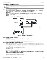
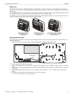
Connections are made from TB2 on the IPOTS-COM board to the to terminal on the GSM card as shown below.
2.8.2 PWRMOD24 NAC Expander
The PWRMOD24 is an optional module that provides an additional 3 amps of NAC power.
Installation and Wiring
Install the PWRMOD24 as described in the Product Installation Document #LS10185-000GE-E.
2.8.3 4XTMF Transmitter Module Installation
The 4XTMF provides a supervised output for a local energy municipal box transmitter in addition to alarm and trouble reverse polarity.
A jumper option allows the reverse polarity circuit to open with a system trouble condition if no alarm condition exists. A disable switch
allows disabling of the transmitter output during testing to prevent accidental calling of the monitoring service.
Local Energy Municipal Box Service (NFPA 72 Auxiliary Fire Alarm Systems):
Supervisory Current: 5.0 mA
Trip Current: 350 mA (subtracted from notification appliance power)
Coil Voltage: 3.65 VDC
Maximum Coil Resistance: 14.6 ohms
Maximum allowable wire resistance between panel and trip coil: 3 ohms
Municipal Box wiring can leave the building
Remote Station Service (NFPA 72 Remote Station Fire Alarm Systems) - Intended for connection to a polarity reversal circuit or
a Remote Station receiving unit having compatible ratings:
Maximum load for each circuit: 10 mA
Reverse polarity output voltage: 24 VDC
Remote Alarm and Remote Trouble wiring can leave the building
!
WARNING: RISK OF ELECTRIC SHOCK AND EQUIPMENT DAMAGE
DISCONNECT ALL SOURCES OF POWER (AC AND DC) BEFORE INSTALLING OR REMOVING ANY MODULES OR
WIRING.
- + A B
-
+
B
A
SW2
SW3
Figure 2.14 Wiring the CELL-CAB/CELL-MOD
IPOTS-COM
CELL-CAB/CELL-MOD
e
s
to
c
e
llc
a
b
.w
m
f

