ES-200X Series Manual —
P/N LS10131-000FL-E:C 7/25/2018
39
Optional Module Installation
Installation
Programming
Following installation and wiring of the ANN-100 LCD annunciator to the FACP, the annunciator must be added to the system via FACP
programming. Refer to the programming section titled “ANN-BUS Setup” on page 90 in this manual for detailed programming informa-
tion.
Trouble Response
If the ANN-100 is installed but the ANN-BUS is not enabled at the FACP, the ANN-100 will indicate a trouble condition by NOT turn-
ing on its AC Power indicator. The LCD will also display
Key Bus Trouble
and the piezo will sound approximately once every 10 sec-
onds. Note that the FACP will provide no indication of an ANN-100 trouble.
To clear the ANN-100 trouble condition, enable the ANN-BUS and program the address corresponding to the address set on the ANN-
100 at the FACP.
ANN-S/PG Serial/Parallel Interface Module
Installation
1.
Ensure that all power (AC and DC) has been removed from the FACP.
2.
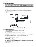
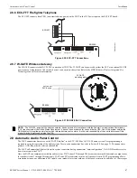
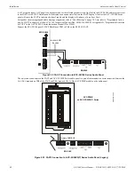
Connect the ANN-S/PG to the FACP as illustrated in Figure 2.21
3.
Using the DIP switches on the back of the ANN-S/PG module, assign an ID number (address) to the module.
4.
Select the address and configuration options for the ANN-S/PG module as described in the Programming section of this manual
(refer to “ANN-BUS Setup” on page 90).
Note that the Auto-configure feature allows the programmer to quickly bring all installed ANN-BUS modules online (refer to
“Auto-Configure” on page 97).
5.
Connect a printer to the ANN-S/PG Parallel or Serial connectors (refer to Figure 2.21). Only one printer can be connected.
Specifications
•
Operating Voltage: 24 VDC
•
Current (Alarm and Standby): 45 mA
•
Ambient Temperature: 32°F to 120°F (0°C to 49°C)
•
Max. Wiring Distance from FACP: 6,000 ft. (1,800 m)
•
Mounting: Surface
•
Dimensions: 6”W x 7-3/4”H x 1-7/16”D (15.2 cm W x 19.7 cm H x 3.7 cm D)
•
For indoor use in a dry location only
Connecting a PRN-7 Printer
Remote printers require a primary AC power source. If required for the fire alarm system configuration (for example, a Proprietary Fire
Alarm System), a remote printer requires a secondary power source (battery backup). Since a secondary power source is not provided as
a standard feature, a separate UL-listed Uninterruptible Power Supply (UPS) should be used. The building emergency power supply may
be used, as long as it meets the power continuity requirements of NFPA 72. Refer to NFPA 72 for further details.
Connect the remote printer to the FACP via the ANN-S/PG module using a standard DB-9 cable. One end of the cable will plug into the
DB-9 connector on the PRN-7 printer and the other end plugs into the serial connector on the ANN-S/PG module.
(-)
(+)
A
B
Figure 2.21 ANN-S/PG Connection to FACP
ANN-S/PG Module
ES-200X
Cable Connectors for
connection to printer
Parallel
Serial
ANN-BUS and power wiring are
supervised and power-limited
24 VDC
nonresettable
Primary
ANN-BUS
9
2
u
d
b
ls
c
to
s
p
g
.w
m
f


