Fire Sentry FS7-130-SX and FS-130-SX2
Controllers
Installation Guide and Operating Manual
MAN0933_V1_1521-001_Rev E_08-12
Page 2
1.1.3 FirePic
FirePic’s digital spectral data provides information facilitating the analysis of the
probable cause of the fire. This data can be used to prevent a subsequent,
potentially damaging fire from occurring. FSC’s proprietary FirePic stores the pre-
fire and actual Detector sensor spectral data of the last 6 fire events in the
Detector’s non-volatile digital memory for analysis. FirePicTM provides the
numerical spectral evidence to determine the cause of the fire. The FirePic records
the time and date for each fire event. The FirePic data includes graphical display of
the relative spectral intensities versus time preceding and during the fire.
Note: To access FirePic, a PC computer with FSC SX Software is required.
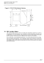
1.2 FS7-2173 Electro-Optical Fire Detector
The FS7-2173 Electro-Optical Fire Detector, with its Wide Band spectral sensor array, is
designed to see all types of hydrocarbon and non-hydrocarbon fires. The FS7-2173 Fire
Detector incorporates a multi-spectral sensor array consisting of Wide Band IR TM, Near Band
IR TM, and Visible Band sensors. The Detector features a 120-degree conical Field-of-View.
The internal microcomputer with signal processing algorithms continuously monitors the
Detector’s circuitry and verifies proper operation. When a Detector declares an ALERT or
ALARM, it communicates with the Controller through the FireBusIITM.
The FS7-2173 Detector’s LED blinks ON every 10 seconds to indicate POWER ON, rapidly
blinks for ALERT and lights up continuously when ALARM is declared. The FS7-2173 Detector
communicates to the Controller via the 4-wire FireBusII RS-485 interface.
The FS7-2173 Detector electro-optics electronics printed circuit board is housed in a
polypropylene leak-proof acid-resistant enclosure.
1.3 FS7-130-SX / -SX2 Controller
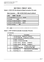
The Model FS7-130-SX / -SX2 Controller is designed for installation into fire control cabinets.
The Controller has 6 built-in SPST relays for interfacing to UL/FM Approved Fire Alarm Panels
for up to 4 Zones of ALARM / ALERT, one master ALERT and one Fault relay.
A maximum of twelve 12 FS7-2173 Detectors can be connected to each Controller with up to 4
Zone assignments. If any Detector is removed, disabled, or fails, the Model FS7-130-SX
or
SX2
Controller issues a Fault Status and displays it with a built-in Fault LED.
The FS7 Controller's integral computer directs the overall operation and performs the following:
•
Provides 12 VDC electrical power for each FS7-2173 Detector.
•
Communicates with the Detectors via the digital RS-485 based FireBus
II
•
Communicates data externally through RS-232 communication channel for system set-up
and diagnostics with FirePic using a PC Computer and SX Software
•
Stores Event History Tables, which contain the time and date stamped ALERT, ALARM,
and Fault histories in non-volatile digital memory.
•
Color LED’s Display the System Status of:
Green
-
POWER ON
(Normal Operation),
Yellow
-
COMM
(communication / improper wiring or loose connections)
Fault
,
Yellow
-
SYSTEM Fault
and 4
Red
-
ALERT
(blinking) /
ALARM
(steady on) for each Zone.
•
Activates Alarm Zone relays during ALARM condition.
•
Activates Master Alert relay during ALERT condition.


