background image

T7047C,G,H REMOTE SPACE SENSORS

62-0179

6

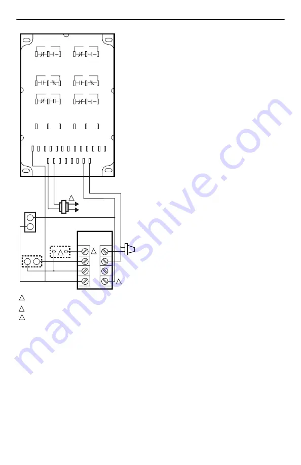
Fig. 17. T7047C1082 used as a remote 

sensor with T7080B Thermostat.

1

POWER SUPPLY.  PROVIDE DISCONNECT MEANS AND OVERLOAD 
PROTECTION AS REQUIRED.

TERMINALS 3, 7 AND 8 ARE ALL EQUIVALENT COMMON TERMINALS.

RESISTOR AND TIME SWITCH IN SERIES BETWEEN TERMINALS 5-7.  
SEE FIG. 6, PAGE 5.

2

M5355

3

L1 
(HOT)

L2

1

2

2

3

4

2

5

6

7

1

8

T

T

T7080 FOR ZONE 1

C1

H1

C2

H2

C3

H3

C

HI

LO

HT

1

2

3

4

5

6

7

8

9 10 11 12

W7080A

LOAD ANALYZER

R

C

3

NIGHT 
SETBACK
RESISTANCE

T7047C1082
(USED WITH 
T7080B ONLY)

ZONE 1
DAMPER
MOTOR
M734J

COMMON

1. THE W7080 REQUIRES SEPARATE TRANSFORMER.
    DO NOT GROUND SECONDARY.
2. EACH M744, M745 MOTOR REQUIRES SEPARATE
    TRANSFORMER. DO NOT GROUND SECONDARY.

ZONES

24 VAC

24 VDC

+

C7100B
DISCHARGE 
AIR 
SENSOR

Summary of Contents for G

Page 1: ...or with no internal adjustment means requires remote setpoint device such as S963B T7067B and T7080B T7047C1009 2 wire remote sensor for use with control systems such as M7044 and M7045 Motors T7047C1025 2 wire remote sensor for use with control systems such as the W927 W960 and W973 T7047C1082 2 wire remote sensor for use with T7080B Transmitter in W7080 Multizone Control System T7047G 2 wire rem...

Page 2: ... ohms for each 1 F 0 6 C temperature change at typical ambient room temperature T7047G 710 ohms nominal at 75 F 24 C resistance changes 7 5 ohms for each 1 F 0 6 C temperature change For the following positive temperature coefficient PTC device resistance increases as temperature increases see Fig 7 T7047H 1093 ohms nominal at 75 F 24 C resistance changes 2 ohms for each 1 F 0 6 C temperature chan...

Page 3: ...ect the proper screws for the application Four mounting screws are provided a Two self tapping type for wall mounting b Two for outlet box mounting 6 If air drafts occur through the wall opening eliminate with suitable material 7 Fasten the T7047 on the wall or outlet box with screws through the mounting holes in the device See Fig 2 8 Replace the cover and tighten the cover locking screw Fig 2 Mo...

Page 4: ...trolled equipment case Fig 8 Internal schematic and typical wiring for T7047C1009 Fig 9 T7047C1025 connected to W960 or W927 panel with internal setpoint adjustment Fig 10 Two T7047C1025 Sensors and one T7047G1000 Sensor providing a temperature averaging network for a T7300 Q7300 Thermostat Subbase Fig 11 Typical wiring for T7047H1008 to Excel 80 100 500 600 Controller 1000 900 800 700 600 500 10 ...

Page 5: ...ER SUPPLY PROVIDE DISCONNECT MEANS AND OVERLOAD PROTECTION AS REQUIRED TERMINAL 8 IS USED WITH THE W974A B ONLY TERMINAL 6 IS USED WITH THE W974A B AND OR REMOTE SENSING ELEMENT T7067B ONLY TERMINALS 6 AND 7 ARE USED TO CONNECT THE REMOTE SENSING ELEMENT TO THE T7067B ONLY NO SCREW IS PROVIDED WITH THE T7067A FOR TERMINAL 7 DOTTED LINES SHOW REMOTE SENSING ELEMENT CONNECTIONS 2 C7046A DISCHARGE AI...

Page 6: ...RIES BETWEEN TERMINALS 5 7 SEE FIG 6 PAGE 5 2 M5355 3 L1 HOT L2 1 2 2 3 4 2 5 6 7 1 8 T T T7080 FOR ZONE 1 C1 H1 C2 H2 C3 H3 C HI LO HT 1 2 3 4 5 6 7 8 9 10 11 12 W7080A LOAD ANALYZER R C 3 NIGHT SETBACK RESISTANCE T7047C1082 USED WITH T7080B ONLY ZONE 1 DAMPER MOTOR M734J COMMON 1 THE W7080 REQUIRES SEPARATE TRANSFORMER DO NOT GROUND SECONDARY 2 EACH M744 M745 MOTOR REQUIRES SEPARATE TRANSFORMER ...

Page 7: ...uits react to rebalance the circuit damper or valve movement or sequential staging of heating and or cooling equipment occurs Low Range Thermostat Use caution when setting temperatures below 40 F 5 C A low temperature setpoint can result in temperatures below freezing in areas distant from the remote sensor Calibration The T7047 Remote Space Sensor is accurately calibrated at the factory It cannot...

Page 8: ...n U S A on recycled paper containing at least 10 post consumer paper fibers Home and Building Control Home and Building Control Honeywell Honeywell Limited Honeywell Limitée 1985 Douglas Drive North 35 Dynamic Drive Golden Valley MN 55422 Scarborough Ontario M1V 4Z9 ...

Reviews: