background image

S3 Series UL Listing Document —

 P/N LS10005-051GF-E:D3  3/09/2016

31

Power Output Circuits

Installation Wiring

2.11  Power Output Circuits

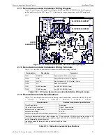
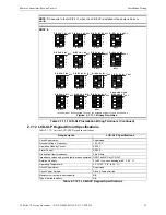
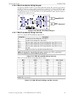
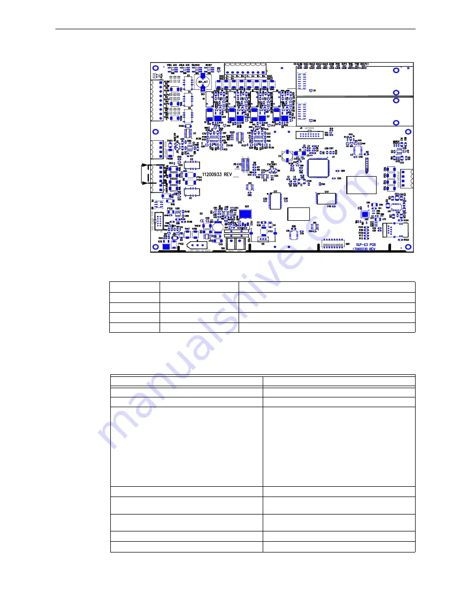
Figure 2.11.1 illustrates the location of the power output circuits for the SLP main board panel.

Figure 2.11.1 Power Output Circuits

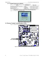
Table 2.11.1 lists the power output circuit terminal wiring designations.

2.11.1  Power Output Specifications

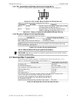
Table 2.11.1.1 lists the power output specifications.

S LP -E 3

S LC -P M /S LC 95-P M   #2

S LC -P M /S LC 95-P M   #1

TB 4

TB 3

TB 2

TB 1

TB 5

B A R   C O D E  

L A B E L

P R O D U C T  

S E R IA L   N U M B E R

P R O D U C T  

D A T E   C O D E  

L A B E L

E T H E R N E T

J2

W 1

J7

P O W E R

O U TP U T 

C IR C U ITS

B- B+

J1

J5

J6 J1

Designation

Description Comments

TB2-1


RESET B+

Resettable 24 VDC Auxiliary Power

TB2-2 

GND

Resettable Power Common Negative

TB2-3 

AUX B+

Non-resettable 24 VDC Auxiliary Power

TB2-4 NC

Make 

No 

Connection

Table 2.11.1 Power Output Circuit - Installation Wiring Terminals

Requirements

 Power Output Specifications

Circuit Supervision:

Supervised

If the circuit is power-limited:

Class 2 Power-Limited

For Special Applications Notification Appliances, there 
shall be a list of devices with the manufacturer and part 
number information that can be connected when NAC 
is selected as a special application.

Max. Alarm Load: - 
Class A, 2.0 A/circuit Special Applications @ 24 VDC 
nominal
Class B, 2.0 A/circuit Special Applications @ 24 VDC 
nominal
Class A, 0.2 A/circuit Regulated @ 24 VDC nominal
Class B, 0.2 A/circuit Regulated @ 24 VDC nominal

NOTE: For additional information on the compatible 
devices with the Manufacturer’s name and model 
number, refer to the Compatibility Addendum for 
Gamewell-FCI Manuals.

For Regulated Output:

0.2A at 24 VDC nominal

Identify the Manufacturer’s Name, model designation 
for appliances to be used on the circuit.

Refer to the Compatibility Addendum to Gamewell-FCI 
Manuals, P/N: 9000-0427-L8.

Impedance values for testing at which ground faults are 
annunciated when ground faults affect operation.

Zero Ohms

Power output circuit battery backed-up or not.

Yes

See General Wiring for duplicate terminal requirements.

N/A

Table 2.11.1.1 Power Output Specifications

Summary of Contents for Gamewell FCI S3 Series

Page 1: ...D3 P N LS10005 051GF E D3 ECN 15 0375 Document LS10005 051GF E 3 09 2016 Rev S3 Series System Small Addressable Fire Alarm Control Panel Underwriters Laboratories Listing Document ...

Page 2: ...ay not provide adequate warning of a fire Smoke detectors cannot be expected to provide adequate warn ing of fires caused by arson children playing with matches especially in bedrooms smoking in bed and violent explosions caused by escaping gas improper storage of flammable materi als etc Heat detectors do not sense particles of combustion and alarm only when heat on their sensors increases at a p...

Page 3: ...o do so can damage circuits Remove all electronic assemblies prior to any drilling filing reaming or punching of the enclosure When possible make all cable entries from the sides or rear Before making modifi cations verify that they will not interfere with battery trans former or printed circuit board location Do not tighten screw terminals more than 9 in lbs Over tightening may damage threads res...

Page 4: ... appropriate version for a specific application Documentation Feedback Your feedback helps us keep our documentation up to date and accurate If you have any comments or suggestions about our online Help or printed manuals you can email us Please include the following information Product name and version number if applicable Printed manual or online Help Topic Title for online Help Page number for ...

Page 5: ...and Ratings 17 2 6 2 SLC PM Installation Wiring Diagram System Sensor 18 2 6 3 SLC PM Installation Wiring Designations 18 2 6 4 SLC PM Signaling Line Circuit Specifications 18 2 6 5 SLC95 PM Installation Wiring Diagram Apollo 19 2 6 6 SLC95 PM Installation Wiring Designations 19 2 6 7 SLC95 PM Signaling Line Circuit Specifications 19 2 7 Remote Annunciator Keypad Circuits 20 2 7 1 ANU 48 Remote An...
Page 6: ...7 1 S3 Series B Size Cabinet Class 2 Power Limited Non Power Limited Wiring Requirements 38 2 18 E3 Series Cabinet A2 Assembly 40 2 18 1 E3 Series Cabinet A2 Installation 40 2 19 E3BB FLUSH LCD Cabinet A2 Assembly 41 2 19 1 E3BB FLUSH LCD Cabinet A2 Installation 41 2 20 S3 Series System Configuration 43 Section 3 Operation 44 3 1 LCD SLP Operation 44 3 1 1 LCD SLP Panel Display Operation 44 3 1 2 ...

Page 7: ...Table of Contents S3 Series UL Listing Document P N LS10005 051GF E D3 3 09 2016 7 8 3 S3 Series Module System Configurations 56 Section 9 System Power Size 57 Index 58 ...

Page 8: ...itle ULLDs LS10080 051GF E E3 Series Fire System UL Listing Document Manuals 9000 0575 E3 Series Broadband Installation Operation Manual 9000 0577 E3 Series Classic Installation Operation Manual Installation Instructions 9000 0491 LCD 7100 Remote Serial Annunciator Installation Instructions 9000 0550 ASM 16 Addressable Switch Module Installation Instructions 9000 0564 ANU 48 Remote LED Driver Annu...

Page 9: ... NFPA 16 Standard for Foam Water Sprinkler and Foam Water Spray Systems NFPA 72 National Fire Alarm Code Central Station Fire Alarm Systems Local Fire Alarm Systems Auxiliary Fire Alarm Systems Remote Station Fire Alarm Systems Proprietary Fire Alarm Systems NOTE Positive Alarm Sequence Standard UL 864 requires that PAS Positive Alarm Sequence be used only for alarm signals from automatic alarm de...

Page 10: ...FML E3 Fiber Optic Multi Mode FSL E3 Fiber Optic Single Mode FLPS 7 7 Amp Power Supply L1 GROUND L2 JP6 JP5 FLPS 7 J1 Designation Description Designation Description L1 AC Power Hot J1 Power output connector EARTH Earth Ground JP5 Factory set to 120 VAC L2 AC Power Neutral JP6 Factory set to 120 VAC Table 2 1 2 1 FLPS 7 Installation Wiring Terminals Requirements FLPS 7 Specifications Circuit Super...

Page 11: ...B1 2 NAC 1 B Notification Appliance Circuit 1 B TB1 3 NAC 1 A NAC 3 B Notification Appliance Circuit 1 Class A RETURN or Notification Appliance Circuit 3 B TB1 4 NAC 1 A NAC 3 B Notification Appliance Circuit 1 Class A RETURN or Notification Appliance Circuit 3 B TB1 5 NAC 2 B Notification Appliance Circuit 2 B TB1 6 NAC 2 B Notification Appliance Circuit 2 B TB1 7 NAC 2 A NAC 4 B Notification App...

Page 12: ...LC 1 Disconnect SLC1 disconnect ON to disconnect normally OFF See Note 4 SW1 2 SLC 2 Disconnect SLC2 disconnect ON to disconnect normally OFF See Note 4 SW1 3 NAC 1 NAC 4 Disconnect NAC1 NAC4 disconnect ON to disconnect normally OFF See Note 4 SW1 4 Buzzer Disable The main SLP E3 Buzzer disable ON to suppress local buzzer normally OFF on the SLP E3 See Note 4 SW1 5 RS 232 BAUD Rate Configure RS 23...

Page 13: ...RIAL NUMBER PRODUCT DATE CODE LABEL ETHERNET J2 W1 J7 J3 JTAG TB1 TB1 W3 TB6 BAT BAT J1 J5 J6 J4 SW5 SW4 SW3 SW2 FLPS 7 MAIN CIRCUIT SUPPLY L1 GROUND L2 NOTE 1 INTERNAL BATTERIES FROM SLP E3 TB6 NON POWER LIMITED USE 12 AH BATTERIES NOTE 2 EXTERNAL BATTERIES FROM SLP E3 TB6 NON POWER LIMITED USE 12 TO 55 AH BATTERIES B B WARNING INSTALLTHE SLC PM SLC95 PM COMPONENT SIDE UP J6 J1 J1 SEE WARNING SEE...

Page 14: ...rol See Note 3 0 030 A 0 065 A LCD E3 LCD Display Switch Control 0 024 A 0 028 A ASM 16 Annunciator Switch Module 0 011 amp with no LEDs lit 0 011 amp SeeNote4 ANU 48 Remote LED Driver Assembly 0 011 amp 0 011 amp See Note 5 LCD 7100 RAN 7100 Remote Display Module 0 12 A 0 23 A DACT E3 Digital Dialer Communication Transmitter 0 018 A 0 018 A RPT E3 UTP ARCNet Repeater 0 016 A 0 017 A FML E3 Fiber ...

Page 15: ...n refer to the CAMWorks Online Help Figure 2 4 1 1 Notification Appliance Circuits See Figure 2 4 1 1 for wiring information For a list of the approved compatible devices refer to the Compatibility Addendum to Gamewell FCI Manuals P N 9000 0427 L8 L8 Class B Style Y Class A Style Z NAC 1 TB1 1 B NAC 1 TB1 1 B NAC 1 TB1 2 B NAC 1 TB1 3 A NAC 2 TB1 5 B NAC 1 TB1 2 B NAC 2 TB1 6 B NAC 1 TB1 4 A NAC 3...

Page 16: ... Manuals P N 9000 0427 L8 L8 Each NAC identify if synchronized NAC appliance are permitted If synchronized NAC appliances employed specify max per circuit if exceeds loading calculations 2 0 amps circuit Full wave rectified voltages identified Uses filtered DC voltages EOL Resistor Part Number or value 6 2 K 47 K 1 4 W or higher or 3 2 K 6 2 K 1 2W or higher or 1 5 K 3 2 K 1W or higher Identified ...

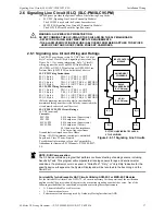
Page 17: ...rkings indicate the polarity that should be maintained throughout the circuit Polarity connected to the circuit must be observed on all devices SLC PM SLC95 PM Circuit Ratings 24 VDC nominal Currents SLC PM 0 014 amp max Supervisory SLC PM 0 014 amp max Alarm SLC95 PM 0 016 amp max Supervisory SLC95 PM 0 016 amp max Alarm 40 Ohms max line impedance 0 5 µf max line capacitance Ground fault test imp...

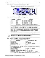
Page 18: ... and A For Style 7 Class X wire the same as Style 6 and use the M500X Isolator Modules per the recommendations as required NOTE 2 Mount the SLC PM board component side up Insert the connector pins extending from J5 on the SLP E3 to the J1 connector underneath the SLC PM board For additional information refer to the Warning and the SLC PM SLC95 PM Installation Instructions P N LS10044 000GF E Table...

Page 19: ...iring to A and A For Style 7 Class X wire the same as Style 6 and use the XP95 LI Line Isolator and XP95 LIB Isolator Base per the recommendations as required NOTE 2 Mount the SLC95 PM board component side up Insert the connector pins extending from J6 on the SLP E3 to the J1 connector underneath the SLC95 PM board For additional information refer to the Warning and the SLC PM SLC95 PM Installatio...

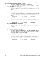
Page 20: ...0491 2 7 4 RAN 7100 Remote Annunciator In the S3 Series System you can use up to five RAN 7100 remote annunciators to remotely connect to the SLP E3 panel For information on the following refer to the RAN 7100 Installation Instructions Part Num ber 9001 0066 2 7 5 LCD SLP Remote Annunciator In the S3 Series System you can use up to fifteen LCD SLP remote annunciators to remotely connect to the SLP...

Page 21: ...NNUNCIATORS W1 J7 B B J1 J5 J6 J1 Designation Description Comments TB2 1 RESET B Resettable 24 VDC Auxiliary Power TB2 2 GND Resettable Power Common Negative TB2 3 AUX B Non Resettable 24 VDC Auxiliary Power TB2 4 NC Make No Connection TB3 1 RS485 Interface Aux RS485 COMM A Output TB3 2 RS485 Interface Aux RS485 COMM B Output Table 2 7 8 1 S3 Series Remote Annunciator Installation Wiring Terminals...

Page 22: ...munications OUT See Note 2 TB1 4 RS 485B Communications OUT See Note 2 TB2 1 24 V 24 V non resettable power IN See Notes 1 2 TB2 2 GND IN GROUND IN See Notes 1 2 TB2 3 24 V OUT 24 V non resettable power OUT See Note 2 TB2 4 GND OUT GROUND OUT See Note 2 TB2 5 GND Extra Ground TB2 6 Earth Ground Earth Ground J5 Local Connection RS 485 communications and power ribbon cable local only See Note 3 J6 K...

Page 23: ...6 D IS P L A Y 7 4 3 2 1 S W 1 O F F O F F 4 3 2 1 4 3 2 1 4 3 2 1 4 3 2 1 S W 1 S W 1 S W 1 S W 1 D IS P L A Y 9 D IS P L A Y 10 D IS P L A Y 11 D IS P L A Y 12 O F F O F F O F F O F F O F F D IS P L A Y 13 4 3 2 1 S W 1 4 3 2 1 S W 1 D IS P L A Y 14 D IS P L A Y 0 4 3 2 1 S W 1 O F F O F F U N S U P E R V IS E D 4 3 2 1 S W 1 D IS P L A Y 8 O F F D IS P L A Y 15 4 3 2 1 S W 1 O F F Requirements ...

Page 24: ...n the SLP main board panel Figure 2 8 1 Reverse Polarity Communication Line Circuit Cabinet Part Numbers Dimensions SLP BB cabinet also called the B Slim cabinet SLP BB 14 1 2 W x 20 1 8 H x 4 1 2 D S3 Series B Size Cabinet S3BB BB RB 19 38 W x 19 38 H x 4 50 D E3 Series Cabinet A2 E3BB BA2 RA2 13 25 W x 10 00 H x 3 00 D E3BB FLUSH LCD Cabinet A2 E3BB FLUSH LCD 13 25 W x 10 00 H x 4 50 D Table 2 7...

Page 25: ...cuit Installation Wiring Terminals Requirements Reverse Polarity Specifications Circuit supervision Not Supervised Max voltage rated current and frequency 24 VDC 0 012 amps NOTE Supervision of a polarity reversal circuit is performed by the Remote Station Receiving Unit not the fire alarm control panel Table 2 8 2 1 Reverse Polarity Specifications DISCLAIMER Intended for connection to a polarity r...

Page 26: ...g terminal designations refer to the following documents RPT E3 UTP Installation Instructions P N 9000 0580 FML E3 FSL E3 Installation Instructions P N LS10046 000GF E You can download these documents from the Gamewell FCI Website www gamewell fci com 2 10 2 RPT E3 UTP Communication Circuit Specifications Table 2 10 2 1 lists the RPT E3 UTP communication circuit specifications 2 10 3 RPT E3 UTP In...
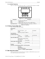
Page 27: ...s B Size cabinets J1 Switch RS485 Termination ON Terminated OFF Un Terminated J2 GFI Switch ON Network ground fault supervision enabled OFF Disabled J3 GND FLT Switch ON Earth ground drive enabled OFF Disabled J4 Factory Use Factory use J5 Fiber Module 1 Connection of optional Fiber Optic module FML E3 or FSL E3 for network Port 1 J6 Fiber Module 2 Connection of optional Fiber Optic module FML E3 ...

Page 28: ...ES ON on 1 7 8 4 6 5 3 2 SW1 LEGEND SWITCH ON SWITCH OFF E3 SERIES ILI MB E3 ILI95 MB E3 NGA ALL SWITCHES OFF on 1 7 8 4 6 5 3 2 SW1 NOTE TO SET THE NODE ADDRESS FOR THE E3 SERIES DO NOT USE SW1 ON THE RPT E3 UTP INSTEAD USE THE SW1 ON THE ILI MB E3 ILI95 MB E3 on on on on on on on on on on on on on on on on on on on on on on on on on on on on on on on on 44 45 54 35 36 9 8 7 5 6 4 2 3 12 14 13 15...

Page 29: ... 7 2 lists the FML E3 switch settings and drive currents FML E3 J2 J1 FIBER IN FIBER OUT Designation Description J1 Connects to the transmitting fiber See Note 1 J2 Connect to the receiving fiber See Note 1 SW1 1 Sets the optical output power for the transmitting fiber See Table 2 10 7 2 SW1 2 Sets the optical output power for the transmitting fiber See Table 2 10 7 2 SW1 3 Sets the optical output...

Page 30: ...FSL E3 terminal wiring designations 2 10 10 DACT E3 Communication Circuit Use the DACT E3 as the remote monitoring circuit for the S3 Series System The DACT E3 provides for sep arate transmissions for Alarm versus Trouble and Supervisory Events for the Remote Station Service DACT reporting of primary AC power failure maybe delayed For information on the Programming Features refer to in Section 5 F...

Page 31: ...n Supervised If the circuit is power limited Class 2 Power Limited For Special Applications Notification Appliances there shall be a list of devices with the manufacturer and part number information that can be connected when NAC is selected as a special application Max Alarm Load Class A 2 0 A circuit Special Applications 24 VDC nominal Class B 2 0 A circuit Special Applications 24 VDC nominal Cl...

Page 32: ... Box Remote Station or Releasing Solenoid See Figure 2 12 1 TB2 6 MUNI Negative Output to Local Energy City Box Remote Station or Releasing Solenoid See Figure 2 12 1 Table 2 12 1 Releasing Device Installation Wiring Terminals Requirements Releasing Device Specifications Circuit supervision Supervised Circuit Power Requirements Class 2 Power Limited Maximum voltage rated current and frequency 27 5...
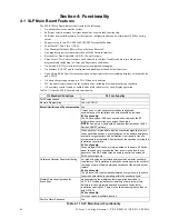
Page 33: ...y contact normally CLOSED N C TB4 2 ALRM NO Alarm relay contact normally OPEN N O TB4 3 ALRM C Alarm relay contact common TB4 4 SUPV NC Supervisory relay contact normally CLOSED N C TB4 5 SUPV NO Supervisory relay contact normally OPEN N O TB4 6 SUPV C Supervisory relay contact common TB4 7 TRBL NC Trouble relay contact normally CLOSED N C TB4 8 TRBL NO Trouble relay contact normally OPEN N C TB4 ...

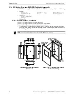
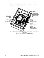
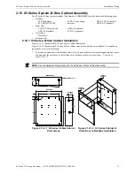
Page 34: ...the backbox refer to the following 1 To mount the SLP BB outer door to the backbox insert four nuts 6 Hex Kep in the four hole mounting pattern and secure the nuts from the outer door to the left side of the backbox as shown in Locations 1 2 3 and 4 of Figure 2 14 1 2 SLP Main Board FLSP 7 Power Supply RPT E3 UTP Optional SLC PM SLC95 PM Batteries DACT E3 Optional NOTE Use the Hardware Kit provide...

Page 35: ...he field wiring as shown in Figure 2 15 1 1 and Figure 2 15 1 2 Unless otherwise indicated on the unit all field wiring circuits are Class 2 power limited except AC power circuit Standby battery circuit Telephone line connections Master Box Releasing Figure 2 15 1 1 illustrates the S3 Series System SLP BB Cabinet Class 2 power limited and non power lim ited wiring extending from the DACT E3 RPT E3...

Page 36: ...l Top Level Circuit Board Configuration DACT E3 RPT E3 UTP FSL E3 1 SLP E3 TB1 TB2 TB1 TB1 FLPS 7 J2 J1 J2 J1 FSL E3 2 SLC PM 2 SLC CIRCUITS FROM SLC PM SYSTEM SENSOR OR SLC95 PM APOLLO TB1 CLASS 2 POWER LIMITED SUPERVISED CONNECT TO PRINTER PORT TB1 SLC PM 1 AUXILIARY RS485 FROM DACT E3 TB2 CLASS 2 POWER LIMITED TELEPHONE LINES FROM DACT E3 TB2 CLASS 2 NON POWER LIMITED NETWORK USING FIBER FROM F...

Page 37: ... To mount the outer door to the backbox insert four 6 nuts in the four hole mounting pattern and secure the nuts from the outer door to the left side of the backbox as shown in Locations 1 2 3 and 4 of Figure 2 16 1 2 SLP Main Board FLPS 7 Power Supply RPT E3 UTP Optional SLC PM SLC95 PM Batteries DACT E3 Optional LCD SLP Display Panel ASM 16 Optional ANU 48 Optional LCD E3 Optional NOTE Use the H...

Page 38: ...ower limited except AC power circuit Standby battery circuit Telephone line connections Master Box Releasing Figure 2 17 1 1 illustrates the S3 Series System B Size cabinet Class 2 power limited and non power limited wiring extending from the SLP E3 and FLPS 7 modules Figure 2 17 1 1 S3 Series B Size Cabinet Class 2 Power Limited and Non Power Limited Wiring Basic Bottom Level Circuit Board Config...

Page 39: ...Non Power Limited Wiring Optional Top Level Circuit Board Configuration DACT E3 RPT E3 UTP FSL E3 2 FSL E3 1 TB1 TB2 TB1 SLC PM 1 SLC PM 2 TB1 SLP E3 TB1 FLPS 7 J2 J1 J2 J1 AUXILIARY RS485 FROM DACT E3 TB2 CLASS 2 POWER LIMITED TELEPHONE LINES FROM DACT E3 TB2 NON POWER LIMITED SLC CIRCUITS FROM SLC PM SYSTEM SENSOR OR SLC95 PM APOLLO TB1 CLASS 2 POWER LIMITED SUPERVISED NETWORK USING FIBER FROM F...

Page 40: ...o the following 1 Mount the outer door to the backbox 2 Insert three nuts 6 32 in the three hole mounting pattern and secure the nuts from the outer door to the left side of the backbox as shown in Locations 1 2 and 3 in the figure below Figure 2 18 1 1 1 illustrates the E3 Series Cabinet A2 outer door to the backbox installation Figure 2 18 1 1 1 E3 Series Cabinet A2 Outer Door to Backbox Install...

Page 41: ...Location 2 in the figure below Figure 2 18 1 2 1 E3 Series Cabinet A2 Sub Assembly to the Inner Door Installation 2 19 E3BB FLUSH LCD Cabinet A2 Assembly The E3 Series E3BB FLUSH LCD Cabinet A2 assembly Part Number E3BB FLUSH LCD typically houses the following units Backbox Outer Door Hardware Kit 2 19 1 E3BB FLUSH LCD Cabinet A2 Installation Figure 2 19 1 1 illustrates the E3 Series E3BB FLUSH LC...

Page 42: ... 6 32 Hex Keps in the eight hole mounting pattern and secure the nuts from the keypad to the front cover as shown in Location 3 in the figure below 4 Plug in the P2 keyswitch cable to the W2 terminal on the LCD SLP display as shown in Location 4 in the figure below 5 Attach the E3BB FLUSH LCD Flush Mount Front Cover to the backbox 6 Insert eight screws 6 32 x 3 8 PHBHD BLK in the eight hole mounti...

Page 43: ...RPT E3 UTP Connects to another RPT E3 UTP SLP E3 or E3 Panel FLPS 7 7 amp Power Supply SLC PM or SLC95 PM connects to SLC Devices See Note 1 J4 J10 SLP E3 Overview Diagram J7 NACs Plug in BATTERIES BATTERIES AC INPUT NON POWER LIMITED NOTE 1 YOU CANNOT COMBINE SLC PM WITH SLC95 PM IF SYSTEM SENSOR USE SLC PM IF APOLLO USE SCL95 PM BATTERY WIRE TB1 DACT E3 WIRING NON POWER LIMITED MUNICIPAL CIRCUIT...

Page 44: ...wledged Hazard blue Lights to indicate a hazard condition Flashes until acknowledged Supervisory yellow Lights when supervisory condition Flashes until event is acknowledged Trouble yellow Lights to indicate trouble condition flashes until trouble is acknowledged Silenced yellow Lights when the System Silence is pressed Flashes when the System Silence is pending It does not reflect the battery con...

Page 45: ...ire drill Reset Initiates a System Reset as well as five User Defined switches User Defined Switches Custom indication and switch function must program in CAMWorks Table 3 1 4 1 Switches FIRE ALARM HAZARD SUPERVISORY TROUBLE AC POWER SILENCED MENU DRILL RESET System Types Local Emergency relocation paging Live Pre Recorded Emergency communication telephone Local with Shunt Protected premise Unit A...

Page 46: ...Yes If cross zone or inter unit synchronization is applicable show details on the limitations and extent should be included S3 Functionality The S3 Series panel NACs are synced alike However the E3 platform does not provide sync across the network NOTE A node is a module with an address that resides on the E3 Series ARCNET network When a system is intended to provide evacuation signaling to more t...

Page 47: ...als locking in the Supervisory signals until manually reset Include instructions or details for selecting the respective operation S3 Functionality Supervisory Latching or Non Latching input devices depend on the assigned device type configured in the CAMWorks Configuration Program Supervisory Non Latching produces a supervisory off normal condition Activates YELLOW supervisory LEDs activates supe...

Page 48: ...he display annunciation at each unit can be simultaneously observed alarm supervisory and trouble conditions as well as reset alarm silence or trouble silence actuation originating at any unit shall be annunciated at each control unit and non supplementary operator interface S3 Functionality Yes on the interconnected control panels the displayed events are prioritized so that users can view only t...

Page 49: ...ry condition processed by Node 1 and the response process begins as follows Supervisory LED Turned ON Supervisory Device location displayed on text display NAC Outputs and Municipal Line Reversal or Releasing Output activated Supervisory sounder activated Supervisory event status message queued for broadcast on network SLC Loop output devices max 250 for 2 loops begin receiving Activate commands o...

Page 50: ...w Programmable Feature Permitted in UL 864 Possible Settings UL Permitted Settings Trouble Reminder Yes Enabled Disabled Enabled Default Supervisory Sounder Cadence Yes Steady Pulsed Steady Pulsed PAS Acknowledge Time Yes 1 to 3600 Seconds 15 Seconds Default PAS Investigate Time Yes 1 to 3600 Seconds 180 Seconds Default Standard NAC Codes Yes Steady Default Temporal 3 ANSI S3 41 Temporal 3 Tempora...

Page 51: ... can be repeated as the new SLC sections are connected or temporarily removed Accept Network Map This mode accepts the current network map Table 5 2 1 1 Main LCD SLP Menu Selections Menu Selection Description Drill ON OFF Is a simple ON or OFF selection ON will activate the NACs while OFF will deactivate the NACs Audible Test Is a simple ON or OFF selection for an Audible Walk Test The NACs will s...

Page 52: ...st configuration change in the S3 Series System It shows a code for the type of the most recent configuration update The INFO Menu provides the following Baud Rates 115200 4800 19200 2400 9600 1200 Table 5 2 5 1 Baud Rates Menu Selection Description Display Log Opens the System Display to all events in the buffer memory Print Log Sends the entire buffer memory to the RS 232 port Clear Log Hard res...

Page 53: ...Check that the green POWER LED lights are on Check that all status LEDs are off Press and hold the LAMP TEST key Verify that all LEDs and all LCD display segments work Activate an Initiating Device Circuit using an alarm initiating device or an addressable initiating device on the SLC and check that all programmed active notification appliances function Reset the alarm initiating device the contro...

Page 54: ...27 You can download the Compatibility Addendum for Gamewell FCI Manuals you can access the Gamewell FCI Website www gamewell fci com In the Compatibility Addendum for Gamewell FCI Manuals the following devices are compatible with the SLP main board panel Sensors Duct Detectors NAC Sync Modules Sensor Bases Two Wire Smoke Detectors Systems NACs Modules Four Wire Smoke Detectors Releasing Solenoids ...

Page 55: ...3 and separately Listed model IPDACT 2 for OT Type Signaling NOTE 2 The designated service type employs peer to peer network sharing information Any SLC PM or SLC95 PM node so designated is acceptable as a Proprietary PPU Table 8 1 1 S3 Series Service Type Applications Accessory Sub Assembly Part Number Description Local Remote Station Rev Pol Proprietary Auxiliary Remote Station DACT Releasing Se...

Page 56: ...ansmitter O See Note 1 ASM 16 Annunciator Switch Sub Assembly O See Note 2 ANU 48 Annunciator Sub Assembly O See Note 2 LCD 7100 Remote LCD Display O See Note 2 RAN 7100 Remote LCD Display O See Note 2 IPDACT IP Digital Alarm Communicator O See Note 2 Legend for Codes in Required Column Y Yes O Optional Separately Listed S1869 S2464 Separately Listed S1949 S1869 Separately Listed Notes Describing ...

Page 57: ... 1 amp Secondary Backup 7 A 55 A H 1 4 amps 7 amps max 24 Hour 5 Minutes N A NOTE The asterisk indicates that the current is based on the Battery Calculation for 4 72 hours Standby Service Table 9 1 Power Supply Currents Accessories Sub Assemblies Networked panels Maximum System Capacity Devices SLC PM System Sensor Devices SLC95 PM Apollo Devices Monitor and Control Modules 318 Modules 252 Module...

Page 58: ...iators ANU 48 20 ASM 16 20 LCD 7100 20 LCD E3 20 LCD SLP 20 RAN 7100 20 S S3 Series Module System Configurations 56 S3 Series System Configuration 43 Signaling Line Circuit 17 Specifications FLPS 7 10 LCD SLP 23 Power Output 31 Relay Circuit 33 Releasing Device Circuit 32 Remote Annunciators 21 Reverse Polarity Circuit 25 RPT E3 UTP 26 SLC95 PM 19 SLC PM 18 SLP E3 13 Standby Battery Calculations A...

Page 59: ... WITH RESPECT TO THE PRODUCTS TRADEMARKS PROGRAMS AND SERVICES RENDERED BY MANUFACTURER INCLUDING WITHOUT LIMITATION INFRINGEMENT TITLE MERCHANTABILITY OR FITNESS FOR ANY PARTICULAR PURPOSE MANUFACTURER SHALL NOT BE LIABLE FOR ANY PERSONAL INJURY OR DEATH WHICH MAY ARISE IN THE COURSE OF OR AS A RESULT OF PERSONAL COMMERCIAL OR INDUSTRIAL USES OF ITS PRODUCTS This document constitutes the only war...

Page 60: ...Gamewell FCI 12 Clintonville Road Northford CT 06472 1610 USA 203 484 7161 fax 203 484 7118 www gamewell fci com ...

Reviews: