56
S3 Series UL Listing Document —
P/N LS10005-051GF-E:D3 3/09/2016
System Configuration
S3 Series Module System Configurations
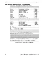
8.3 S3 Series Module System Configurations
Table 8.3.1 lists the Modules required to make the S3 Series System Configuration.
Module
Description
Required?
SLP-E3
Smart Loop Panel - Main Board
Y (See Note 1)
SLC-PM
SLC-PM for System Sensor Protocol
Y (See Note 3)
SLC95-PM
SLC95-PM for Apollo Protocol
Y (See Note 3)
LCD-E3
LCD Display sub-assembly
O (See Note 1, 2)
LCD-SLP
LCD Display-SLP sub-assembly
Y (See Note 1),
O (See Note 2)
FLPS-7
Power Supply
Y (See Note 1)
FML-E3
Fiber-Optic Multi-Mode
O (See Note 1)
FSL-E3
Fiber-Optic Single-Mode
O (See Note 1)
RPT-E3-UTP
Network Repeater sub-assembly
Y (See Note 1)
DACT-E3
Digital Dialer Communicator Transmitter
O (See Note 1)
ASM-16
Annunciator Switch Sub-Assembly
O (See Note 2)
ANU-48
Annunciator Sub-Assembly
O (See Note 2)
LCD-7100
Remote LCD Display
O (See Note 2)
RAN-7100
Remote LCD Display
O (See Note 2)
IPDACT
IP Digital Alarm Communicator
O (See Note 2)
Legend for Codes in Required? Column
Y - Yes
O - Optional
## - Separately Listed (S1869), (S2464)
### - Separately Listed (S1949), (S1869)
#### - Separately Listed
Notes Describing Codes in Required? Column
NOTE 1:
These items are modules that consist of the S3 Series control panel.
NOTE 2:
These items may be remotely located from the Control Panel.
NOTE 3:
One loop driver module is required per SLP-E3 minimum. Select SLC-PM for System
Sensor or select SLC95-PM for Apollo devices. The SLP-E3 supports the use of up to two SLC-
PM or SLC95-PM modules per SLC-E3. Only one type of loop driver module may be installed on
a single SLP-E3. DO NOT use one SLC-PM and one SLC95-PM on a single SLP-E3.
Table 8.3.1 S3 Series Module System Configurations


