40
S3 Series UL Listing Document —
P/N LS10005-051GF-E:D3 3/09/2016
Installation Wiring
E3 Series, Cabinet A2 Assembly
2.18 E3 Series, Cabinet A2 Assembly
The E3 Series, Cabinet A2 assembly (Part Number: E3BB-BA2/RA2) typically houses the following units:
•
Backbox
•
Inner Door
•
Outer Door
– Door Insert
•
Hardware Kit
2.18.1 E3 Series, Cabinet A2 Installation
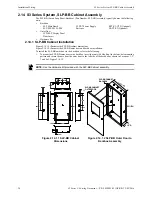
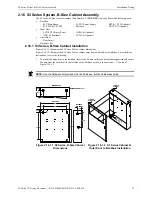
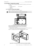
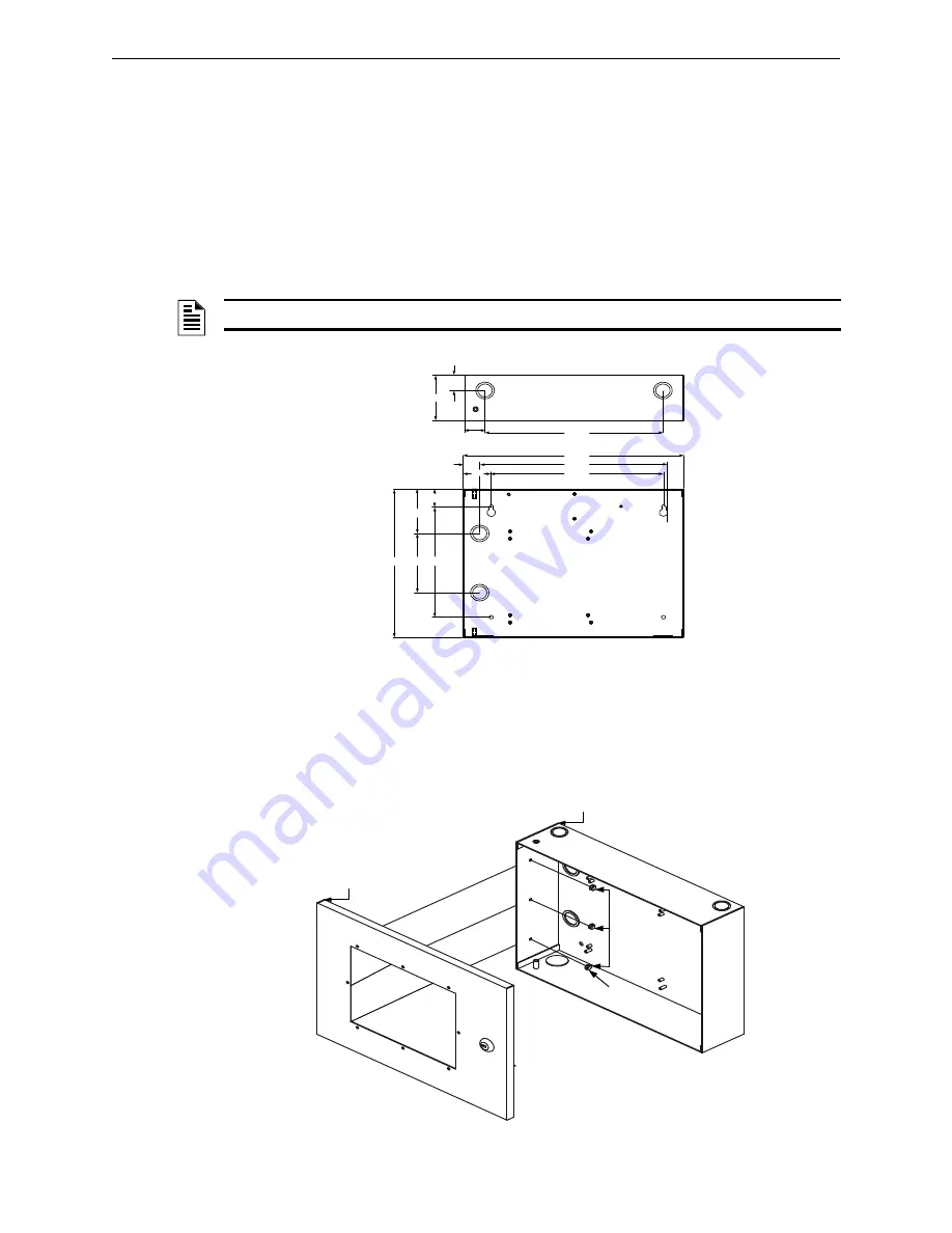
Figure 2.18.1.1 illustrates the E3 Series, Cabinet A2 dimensions.
2.18.1.1 E3 Series Cabinet A2 Outer Door to Backbox Installation
To install the E3 Series Cabinet A2 outer door to the backbox, refer to the following.
1.
Mount the outer door to the backbox.
2.
Insert three nuts (#6-32) in the three-hole mounting pattern and secure the nuts from the outer door to the
left side of the backbox as shown in Locations 1, 2 and 3 in the figure below.
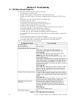
Figure 2.18.1.1.1 illustrates the E3 Series Cabinet A2, outer door to the backbox installation.
Figure 2.18.1.1.1 E3 Series Cabinet A2, Outer Door to Backbox Installation
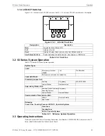
– LCD-SLP Display Panel
– LCD-E3 (Optional)
NOTE:
Use the Hardware Kit provided with the E3 Series, Cabinet A2 assembly.
Figure 2.18.1.1 E3 Series, Cabinet A2 Dimensions
3.00"
.875"
1.25"
10.75"
BACKBOX TOP
10.35"
1.00"
1.70"
1.20"
3.00"
10.00" 4.00" 7.46"
BACKBOX
1
2
3
4
13.25"
11.25"
CABINET A2,
BACKBOX
CABINET A2,
OUTER DOOR
NU
T, H
EX
(#6
-32
)
3 P
LA
CE
S
3
2
1
3
2
1

