9
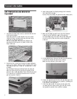
9. Connect the control wires to the correct terminals. The
terminals are clearly marked N1 and N2 for utility sensing; 23
and 194 for transfer relay control; and T1 and 0 for battery
charge. On pre-wired switches, the 0 (zero) wire will not be
present/required.
NOTE:
In order to maintain separation of circuits, the
DC control wires must be separated from the AC
control wires. A piece of fiberglass sleeving has
been provided in the manual kit to achieve this.
Slide the sleeving over the AC wires OR the DC
wires, but not both, from the wire landing area
to the outside of the generator. Use the cable tie
locations to hold the sleeving in place.
10. An improperly connected control wire can damage the
generator control board.
11. For 10-20 kW models, locate the metal hasp that is packaged
in the owner’s manual bag. Insert the hasp in the slot located
on the left side of the external circuit breaker box. Be sure that
the clip of the hasp is facing toward the front of the generator.
If desired, lock the external box.
BATTERY INSTALLATION
1. Before purchasing a battery for the generator, refer to the
Owner’s Manual for the recommended battery.
• Group 26R, 12 Volt, 525cca minimum
2. Follow all of the procedures and safety precautions in the
generator Owner’s Manual when installing the battery.
Verify the switch is in the off position. When preparing for
operational testing, DO NOT connect the battery until transfer
switch connections are complete.
APPENDIX A – RTSX AND RTSD TRANSFER
SWITCH INSTALLATION & OPERATIONAL
TESTING
1. Before beginning any installation, make sure power is shut
OFF to the main distribution panel and carefully read the
Owner’s Manual that came with the transfer switch.
To simplify the installation process, the transfer switch
should be mounted as close to the main distribution panel as
possible. Make sure no water or corrosive substances can
drip onto the transfer switch enclosure.
2. Always inspect the switch for shipping damage. Never mount
a transfer switch that shows any evidence of damage.
3. Protect against impact and mount the switch vertically to a rigid
support structure. Make sure the switch is level and plumb.
Check local codes before wiring the transfer switch. Some
jurisdictions require that wiring inside the switch be done by a
licensed electrician.
Appendix A
Summary of Contents for Generator
Page 1: ...855 GEN INFO INSTALLATION GUIDELINES Air cooled Generators ...
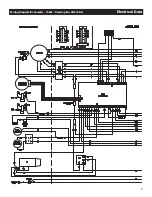
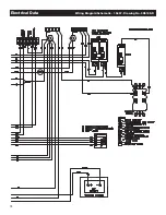
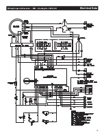
Page 19: ...17 Wiring Diagram Schematic 15kW Drawing No 0H6198 D Electrical Data ...
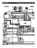
Page 20: ...18 Electrical Data Wiring Diagram Schematic 15kW Drawing No 0H6198 D ...
Page 21: ...19 Wiring Diagram Schematic 15kW Drawing No 0H6198 D Electrical Data ...
Page 22: ...20 Electrical Data Wiring Diagram Schematic 20kW Drawing No 0H7570 B ...
Page 23: ...21 Wiring Diagram Schematic 20kW Drawing No 0H7570 B Electrical Data ...
Page 24: ...22 Electrical Data Wiring Diagram Schematic 20kW Drawing No 0H7570 B ...
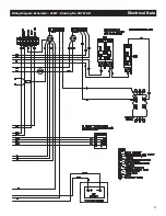
Page 25: ...23 Wiring Diagram Schematic 10kW Drawing No 0J2939 B Electrical Data ...
Page 26: ...24 Electrical Data Wiring Diagram Schematic 10kW Drawing No 0J2939 B ...
Page 27: ...25 Wiring Diagram Schematic 10kW Drawing No 0J2939 B Electrical Data ...


