How to link Mimic LED ‘Shapes’ to system events
Each used LED shape must be linked with a system event, such as:
¨
Device fire
¨
Device fault
¨
Channel fire
¨
Channel fault
¨
Zone fire
¨
Zone fault
¨
Card fire
¨
Card fault or
¨
Supervisory Command Build.
Below is a typical example that shows how a shape can be linked to a zone:
For full information on configuration see the instructions supplied with the
Mimic Configuration tool.
Test
Test the Custom panel and ensure it gives the correct indication for the configured Vigilon System event.
Commissioning information
Mimic LED Driver Card
Gent by Honeywell reserves the right to revise this publication from time to time and make changes to the content hereof without
obligation to notify any person of such revisions of changes.
Hamilton Industrial Park, Waterside Road, Leicester LE5 1TN, UK
Website: www.gent.co.uk
Tel44 (0) 116 246 2000
Fax (UK): +44 (0)116 246 2300
2
4188-951_issue 2_01/12_Part 2_Mimic LED driver
by Honeywell
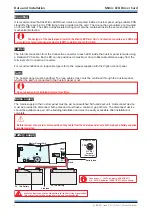
Drag and drop an LED ‘Shape’ onto the
a system event in the system tree. This
example shows
being dropped
onto
so the two are linked.
Shape 5
Zone 5,
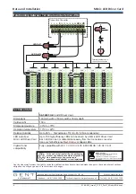
The LED Shape
here is linked to
.
So when
has a fire event then the LED connected
to
terminals
and
will be lit (On).
Note also the
is associated with
IDC Connector
on the
5 P16_26_8
Zone 5 - Fire
Zone 5
26
8
P16
Connection Converter
Connection Converter
Mimic LED Driver Card.


