background image

The following checks and tests should be
conducted on each installed Repeat panel to
ensure the basic functions are operating correctly.

Compatibility

The repeat panel is compatible with system
control panel having card and software stated
below:

Panel Card Software

CARD

EN54

BS5839

LCC

³

V4.00

³

3.42

LPC

New Shorter

Card ONLY

³

V4.19

³

3.90

MCC

³

V4.11

-

MCB

³

V4.21

-

³

means equal to or greater than

"

For a BS Repeat panel ONLY:

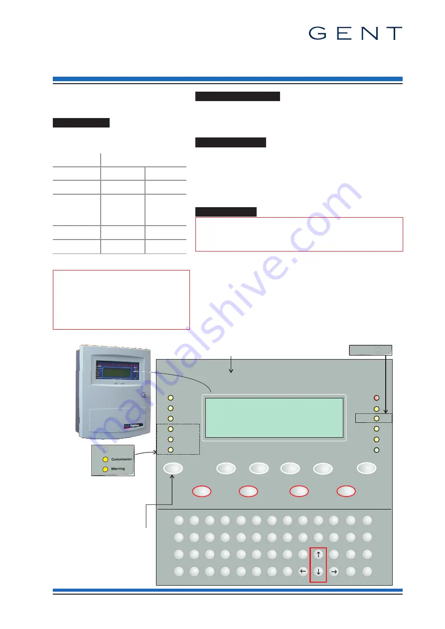
Ensure the membrane labels supplied are
fitted. Also ensure the zonal LEDs are
disabled by setting the links on the DKC,
for details see part 1 of this leaflet.

Buzzer Disable Link

During system commissioning it may be necessary to fit a link (not suppllied)
across P14 on the MRC to disble the local buzzer at the repeat panel. On
completion of all commissioning work ensure the buzzer is enabled by
removing the link.

Test indications

Check to ensure the fault indications are given of typical failure conditions
such as local mains and battery disconnections:

¨

display shows a the Fault event

¨

LED indications are given

¨

local buzzer sounds (Cancel the buzzer using the local
'Cancel buzzer' button).

Test functions

"

When operating the SOUND ALARMS button it will

activate the alarm sounders in the system.

¨

Display test (to ensure all LEDs are working)

¨

Sound Alarms

¨

Silence Alarms

¨

Display of Fire events

¨

Reset

¨

Operation of U1-U4 Function keys (as configured at the
control panel)

¨

Verify (as configured at the control panel)

4188-839_issue 7_08/12_pt2_EN/BS Repeat_inst

1

Commissioning information

Vigilon Repeat panel (EN/BS)

VIG-RPT-72

by Honeywell

Vigilon Fire System

GENT 2010

Panel healthy

15:45

Vigilon Fire System

GENT 2010

Main Panel Healthy

15:45

Fault

System Fault

Test

Fire

Power

Power Fault

CB254

Disablement

Sounder

1

2

3

4

5

6

7

8

9

10

11

12

13

14

15

16

17

18

19

20

21

22

23

24

25

26

27

28

29

30

30

32

Zones

Previous

Next

Delay

Verify

Use the Menu On/Off
and the function keys (F1 - F4)
to navigate through the menus

CB253

1

2

3

4

5

6

7

8

9

0

"

#

$

%

^

&

*

(

+

:

,

-

;

.

)

Q

W

E

R

T

Y

U

I

O

P

U1

U2

U3

U4

Fire

A

S

D

F

G

H

J

K

L

Z

X

C

V

B

N

M

Sound Alarms

Silence Alarms

Reset

Cancel Buzzer

Menu On/Off

F4

F3

F1

F2

!

Insert

Delete

Space

Shift

Enter

;

Verify

BS Repeat panel ONLY

BS Repeat panel ONLY

The Zone indicators are NOT
applicable for

BS Repeat panel.

www.acornfiresecurity.com

www.acornfiresecurity.com

Summary of Contents for GENT VIG-RPT-72

Page 1: ...o 45ºC Relative humidity Non condensing Up to 90 temperature 5 C to 45 C Battery 12V 7Ah sealed lead acid Mains operating voltage 230V 15 10 50 60Hz Rated Current 0 2A Emission BS EN61000 6 3 2001 Immunity BS EN50130 4 1996 Part 4 LVD BS EN 60950 2006 Ingress protection IP31 estimated Colour Door Pantone 422 Back box Graphite Grey RAL 7024 Controls with door closed Access level 1 Next and Previous...

Page 2: ...o terminal block P9 on the Master Repeat Card fit battery lead supplied in the spares to connector P5 on Master Repeat Card connect the loop cables to terminal block P16 on the Master Repeat Card connect the 40 way ribbon cable to the Master Repeat Card connector P2 and the other end to Display Key Card on the top right edge connector P1 connect the 20 way ribbon cable to the Master Repeat Card co...

Page 3: ...e Loop COM Master Repeat Card 01 L1 02 L2 0C LC P9 L N N P17 DANGER BT BT RS485 0V 24V WRITE PROTECT BUZZER DISABLE P8 DANGER DO NOT REMOVE L N P5 FS2 FS4 P16 P4 P2 P1 SW3 PB2 WD1 P14 P7 USB FS3 2A QB RESET DANGER WARNING Removal of cover exposes live parts mains electrical supply Loop OUT Previous Next Spur Connection XXXXX Fire Alarm System GENT 2007 Designed to EN54 Pt 2 4 Panel healthy 15 45 1...

Page 4: ...control buttons must always be left in an enabled state with the control buttons link fitted At the end of their useful life the packaging product and batteries should be disposed of via a suitable recycling centre and in accordance with national or local legislation Do not dispose of with your normal household waste Do not burn WEEE Directive At the end of their useful life the packaging product ...

Page 5: ...r sounds Cancel the buzzer using the local Cancel buzzer button Test functions When operating the SOUND ALARMS button it will activate the alarm sounders in the system Display test to ensure all LEDs are working Sound Alarms Silence Alarms Display of Fire events Reset Operation of U1 U4 Function keys as configured at the control panel Verify as configured at the control panel 4188 839_issue 7_08 1...

Page 6: ...configuration of the system To create or change an existing Engineer PIN You will need to be at Access level 3 if an Engineer PIN is already set up Press the Menu On Off button and select Test Eng UserCode then momentarily press etc to select Config New Pass and then type a new PIN or change an existing PIN and press the Enter key will appear if a PIN is already setup It is recommended that the PI...

Page 7: ...ith Mk4 MRC Menu map Control E C Q Key E Enter C Cancel Q Quit Verify etc Params 0 3 E C Q Timeslot etc Params 1 16 Delay On Params HH MM SS On E C Q Off Off DelayBlk Params 1 16 Delayed E C Q Params MM SS 0 10min End E C Q Stop Group EN BS EN BS Option for BS Repeat panel only Option for EN Repeat panel only Sector Build Params 1 255 E C Q Aux Rly Params 1 2 E C Q Params 1 32 E C Q Enable Disable...

Page 8: ... Params 0 100 Signal C Q E Params 16 100 C Q E Params 0 255 Params 1 100 C Q E etc State enable Params 1 8 Params 0 15 C Q E Params 0 15 State disable TimeBlok etc Voice Tone number Set Up Loop Params 1 207 Device It is important to back up the data at the main control panel following any changes using the in Setup menus at the repeat panel Menus accessible with panel door open and AL2 password Ac...

Page 9: ...8 C Q E N C P R 1 100 Loop Params 1 207 E Params 0 15 Q C E E Params C Q 1 207 Loop Params Fault Disable Exceptions Sub Faults HistFire etc etc Warning Device 1 4 1 32 Params Loop Params 1 255 E C Params Q MCP IO Line Device Device Sector Card etc Params 1 207 C Q E 1 8 Device Params Q E etc Active Historic Events Label UserCode TimeAvg Status etc Loop Map Control Set Up Info Test Eng EN BS Repeat...

Reviews: