background image

GF505 & GF510

Fire Alarm Control Panels

Manual

Document 53164   Rev: B5
6/12/2018    ECN: 18-253

Summary of Contents for GF505

Page 1: ...GF505 GF510 Fire Alarm Control Panels Manual Document 53164 Rev B5 6 12 2018 ECN 18 253 ...

Page 2: ...ide adequate warning of a fire Smoke detectors cannot be expected to provide adequate warning of fires caused by arson children playing with matches especially in bedrooms smoking in bed and violent explosions caused by escaping gas improper storage of flammable materials etc Heat detectors do not sense particles of combustion and alarm only when heat on their sensors increases at a predetermined ...

Page 3: ...can damage circuits Remove all electronic assemblies prior to any drilling filing reaming or punching of the enclosure When possible make all cable entries from the sides or rear Before making modifications verify that they will not interfere with battery transformer or printed circuit board location Do not tighten screw terminals more than 9 in lbs Over tighten ing may damage threads resulting in...

Page 4: ...e version for a specific application Documentation Feedback Your feedback helps us keep our documentation up to date and accurate If you have any comments or suggestions about our online Help or printed manuals you can email us Please include the following information Product name and version number if applicable Printed manual or online Help Topic Title for online Help Page number for printed man...

Page 5: ... for Class A 29 2 7 2 4XTMF Option Module 30 4XTMF Transmitter Module Installation 31 2 7 3 ANN SEC Option Card 32 2 8 ANN BUS Devices 33 Guidelines 33 2 8 1 ANN BUS Wiring 33 Calculating Wiring Distance for ANN BUS Modules 33 Wiring Configuration 34 Powering ANN BUS Devices from Auxiliary Power Supply 36 2 8 2 ANN BUS Device Addressing 36 2 8 3 GFANN 80 Remote Fire Annunciator 37 Specifications 3...

Page 6: ...l Hold 2 Sec 86 4 1 4 Reset 86 4 2 LED Indicators 86 4 3 Normal Operation 86 4 4 Trouble Operation 87 4 5 Alarm Operation 87 4 6 Supervisory Operation 88 4 7 Process Monitor Operation 88 4 8 Hazard Tornado Condition Operation 89 4 9 Medical Alert Condition Operation 89 4 10 Disable Enable Operation 89 4 11 Waterflow Circuits Operation 89 4 12 Detector Functions 89 4 13 Time Functions Real Time Clo...

Page 7: ... to Use Table 7 3 on page 101 to Calculate System Current Draw 100 7 4 Calculating the Battery Size 102 7 4 1 NFPA Battery Requirements 102 7 4 2 Selecting and Locating Batteries 102 Appendix A Ademco Contact ID Format Event Code Descriptions 103 A 1 Transmission Format Between DACT and Receiver 103 A 2 Ademco Contact ID Typical Printout 103 Appendix B NFPA Standard Specific Requirements 108 B 1 C...

Page 8: ...ng Systems UL 1481 Power Supplies for Fire Protective Signaling Systems UL 1638 Visual Signaling Appliances UL 1971 Signaling Devices for Hearing Impaired UL 2017 General Purpose Signaling Devices and Systems Other NEC Article 250 Grounding NEC Article 300 Wiring Methods NEC Article 760 Fire Protective Signaling Systems Applicable Local and State Building Codes Requirements of the Local Authority ...

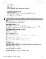
Page 9: ...4 VDC supervised nonpower limited Basic System Connections 5 Zone Panel Power Supply Connector For more specific UL wiring information refer to page 27 Important Removing Ground Fault Disable Jumper JP43 voids UL NFPA Style Class indentifications for circuits Remove jumper JP43 only with the approval of the local AHJ Authority Having Jurisdiction Special Application DC Power Outputs 24 VDC Nonsupe...

Page 10: ... Zone Panel Power Supply Connector For more specific UL wiring information refer to page 27 Important Removing Ground Fault Disable Jumper JP43 voids UL NFPA Style Class indentifications for circuits Remove jumper JP43 only with the approval of the local AHJ Authority Having Jurisdiction Special Application DC Power Outputs 24 VDC Nonsupervised power limited circuits Supervise with a power supervi...

Page 11: ... N U N C I A T O R NAC 4 Fault ZONE 5 ALM TBL SUP 5 ALM TBL SUP NAC 3 Fault Disabled ZONE 4 ALM TBL SUP 4 ZONE 9 ALM TBL SUP 9 FROM AP PHONE PSTN TO AP OUT NC OUT NO INPUT TAMPER GND 12 24V P4 CN2 P5 P6 P7 P8 P9 P10 P11 P12 FCI CHG 120 Charger Doc 52459 ANN BUS TB3 Battery Connector J12 gf510peri wmf GFANN 80 LCD Text Annunciator Doc 53386 GFANN R LED LED Display Doc 53375 GFANN RLY 10 Form C Rela...

Page 12: ... using the PS Tools and the USB port on the FACP Any personal computer with Windows XP or newer compatible modem with a speed of 2400 baud and PS Tools may serve as a Service Terminal This allows download of the entire program or upload of the entire program history file walktest data and current status Activation of a compatible smoke detector or any normally open fire alarm initiating device wil...

Page 13: ...rcuits TB4 and TB6 on GF510 only Alarm Zones 1 5 on TB 4 GF505 Alarm Zones 6 10 on TB6 GF510 only Supervised and power limited circuitry Operation All zones Style B Class B Normal Operating Voltage Nominal 20 VDC Alarm Current 15 mA minimum Short Circuit Current 40 mA max Maximum Loop Resistance 100 ohms 700 ohms per zone for linear heat detection See Section 2 3 Input Circuits for more informa ti...

Page 14: ...compatible listed devices Special Application Primary ANN BUS Power TB3 Operating voltage Nominal 24 VDC Maximum Available Current 500mA Power limited circuit Special Application Secondary ANN BUS Power ANN SEC TB1 Operating voltage Nominal 24 VDC Maximum Available Current 500mA Power limited circuit Remote Sync Output TB2 24 VDC nominal special application power Maximum current is 40 mA End of Li...

Page 15: ...f Refer to the battery calculations section for additional information Standby 1 0 amp max per panel Special Application Nonresettable or Resettable Power Special Application Resettable Power NAC 1 NAC 2 NAC 3 NAC 4 0 5 amp max per circuit 0 5 amp max per circuit 3 0 amps max per circuit 3 0 amps max per circuit 3 0 amps max per circuit 3 0 amps max per circuit Alarm 7 0 amps max per panel Primary...

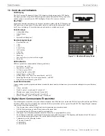
Page 16: ... Piezo Sounder A piezo sounder provides separate and distinct sounds for alarm trouble maintenance process monitor and supervisory conditions as follows Alarm on steady Trouble pulse 1 second on and 1 second off Maintenance pulse 1 second on and 1 second off Supervisory pulse second on and second off Process Monitor pulse second on and second off 1 4 Digital Alarm Communicator Transmitter Two modu...

Page 17: ... The GFANN RLY Module which can be mounted inside the cabinet provides 10 Form C relays ANN SEC Secondary ANN BUS Module The ANN SEC module provides another ANN BUS port for more wiring flexibility TR CE Trim ring A trim ring TR CE is available as an option The trim ring allows semi flush mounting of the cabinet Battery Box BB 55F battery box may be used to house two batteries greater than 18 Amp ...

Page 18: ... equipment must be connected to a properly installed RJ31X jack that is electrically in series with and ahead of all other equipment attached to the same telephone line If there are any questions concerning these instructions consult the telephone company or a quali fied installer about installing the RJ31X jack and alarm dialing equipment Refer to Digital Communicator on page 28 for an illustra t...

Page 19: ...rd and transformer can be easily removed Loosen the two 3 8 nuts securing the top flanges of the chassis then slide the chassis up to free it from the lower tabs Place the chassis assembly in a protective anti static bag in a safe location until it can be reinstalled in the backbox 1 Mark and predrill hole in the wall for the center top keyhole mounting bolt using the dimensions illustrated in Fig...

Page 20: ...Slot for optional Dress Panel Semi Flush mounting hole Mounting slots for optional Trim Ring Hinge Slot for optional Dress Panel Semi Flush Mounting Do not recess box more than 3 875 into wall to avoid covering venting holes on top of box 20 GF505 GF510 Manual P N 53164 B5 6 12 2018 ...

Page 21: ...his does not provide reliable protection Secondary Power Source Batteries Observe polarity when connecting the battery Connect the battery cable to J12 on the main circuit board using the plug in connector and cable provided The battery charger is current limited and capable of charging sealed lead acid batteries The charger shuts off when the system is in alarm Figure 2 3 Backbox and Battery Box ...

Page 22: ...input zones used for linear heat detection The field wiring for each zone is supervised for opens shorts and ground faults All conditions are visually and audibly annunciated Each circuit is configured for Style B Class B operation and will accept i3 smoke detectors any normally open contact devices as well as conventional 2 wire or 4 wire 24 VDC smoke detectors Refer to the Gamewell FCI Device Co...

Page 23: ...vised and power limited 4 7 KΩ watt resistor P N 71252 UL listed compatible 2 wire smoke detectors manual pull stations heat detectors Dummy load all unused circuits 4 7 KΩ watt resistor P N 71245 ms 10UDidc wmf UL listed Power Supervision Relay refer to Device Compatibility Document for list of compatible relays Resettable 24 VDC 4 wire smoke detector power 500 mA maximum UL listed compatible 4 w...

Page 24: ...is cleared and the FACP is reset Supervisory Switch activation causes the panel to latch the supervisory condition if the Combo type code is selected or track the panel will clear when the supervisory condition is cleared if the Combo Autoresettable Supervisory type code is selected 2 4 Output Circuits 2 4 1 Notification Appliance Circuits Total current drawn from the four Style Y Class B Notifica...

Page 25: ...45 Polarized Bell Polarized Strobe Polarized Horn Polarized Horn Polarized Horn Strobe Polarized Bell Notification Appliance Circuit polarity shown in alarm condition ms 10UDnac wmf Ferrite Bead p n 50116546 001 Figure 2 8 Special Application Auxiliary Power Special Application 4 Wire Smoke Detector Power 500 mA 24 VDC filtered resettable power for 4 wire smoke detectors can be obtained from these...

Page 26: ...e control panel s NAC can be synchronized as described in Synchro nized NAC Operation on page 57 Notification appliances connected to remote power sources may require synchronization with the FACP s devices For the GF505 GF510 the Remote Sync Output is not required Synchronization for remote power supplies is provided directly from NAC1 Out 1 Note that NAC 1 Out 1 must be programmed for sync opera...

Page 27: ...ower limited and nonpower limited circuit wir ing must enter and exit the cabinet through different knockouts and or conduits A typical wiring diagram is illustrated below J13 Figure 2 11 Typical UL Power limited Wiring Requirements Power limited Circuits Class 2 Power limited Circuits Class 2 Nonpower limited Circuit AC Power CAC 5X 4XTMF CAC 5X earth ground Nonpower limited Circuit Power limited...

Page 28: ...Premises Equipment and Wiring Telephone Line FACP with DACT Network Service Provider s Facilities Network Demarcation Point RJ31X Jack Unused RJ 11 Jack Unused J 11 Jack Telephone Telephone Telephone Answering System Fax Machine Computer 9050ACTAdact wmf 1 2 3 4 5 6 7 7 8 1 2 3 4 5 6 8 J8 J9 Figure 2 13 Wiring Phone Jacks 10UDJACK2 wmf RJ31X Jack RJ31X Jack Secondary Lines Incoming Telco phone lin...

Page 29: ...r of needle nose pliers to hold the hex nut while securing Carefully align the connector on the CAC 5X with J7 and press the module securely into place Make certain the pins are properly aligned to prevent bending or breaking of any connector pins Secure the top right corners of the CAC 5X to the standoffs with the screw that removed in step 1 and another from the hardware kit Wiring NACs and IDCs...

Page 30: ...nnectors J4 and J5 on the FACP main circuit board being careful not to bend any pins 5 Secure the option module to the standoff on the main circuit board with the supplied screws 6 For proper 4XTM operation the output relays must be programmed for the factory default settings Alarm Relay 1 Trouble Relay 2 and Supervisory Relay 3 7 When the installation has been completed connect the wiring to the ...

Page 31: ...rom notification appliance power Coil Voltage 3 65 VDC Maximum Coil Resistance 14 6 ohms Maximum allowable wire resistance between panel and trip coil 3 ohms Municipal Box wiring can leave the building Remote Station Service NFPA 72 Remote Station Fire Alarm Systems Intended for connection to a polarity reversal circuit or a Remote Station receiving unit having compatible ratings Maximum load for ...

Page 32: ...ard with the supplied screw Figure 2 17 4XTMF Transmitter Module Connect to FACP Connectors J4 J5 Disconnect Switch shown in disconnect position TBL Jumper Remote Alarm Class 2 power limited Remote Trouble Class 2 power limited No connection 1 2 3 4 5 6 7 Polarities are shown for module activation Note the 4XTMF Module is not directly suitable for transmitting reverse polarity supervisory signal F...

Page 33: ...essary to calculate the total worst case current draw for all modules on a single 4 conductor bus The total worst case current draw is calculated by adding the individual worst case currents for each module The individual worst case values are shown in the following table After calculating the total worst case current draw Table 2 2 specifies the maximum distance the modules can be located from th...

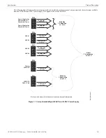
Page 34: ...e 3 731 feet maximum using 16 Gauge wire 5 906 feet maximum using 14 Gauge wire Wiring Configuration Figure 2 19 illustrates the wiring between the FACP s Primary ANN BUS and ANN BUS devices Maximum Wire Length feet 6 000 feet maximum Maximum Resistance Ohms 500 Rpu where Rpu Ohms per 1 000 feet for various Wire Gauges see table below Wire Gauge Ohms per 1 000 feet Rpu 22 16 2 18 6 4 16 4 02 14 2 ...

Page 35: ...via the ANN SEC option card and ANN BUS devices TB1 J1 A B ANN SEC Figure 2 20 FACP wiring to ANN BUS Device on Secondary ANN BUS via ANN SEC FACP GFANN 80 ANN BUS and power wiring are supervised and power limited Secondary ANN BUS ann80to5x2 wmf GF505 GF510 Manual P N 53164 B5 6 12 2018 35 ...

Page 36: ...o be sequen tial and can be set to any number between 01 and 08 Note that 00 is not a valid address The following table shows the DIP switch set ting for each address Figure 2 21 Powering ANN BUS Devices from HPF24S6 8 GFANN 80 GF505 GF510 HPF24S6 8 24 VDC 24 VDC ANN BUS Cut Ground Fault Detection jumper JP1 FACP monitors for ground faults ANN BUS and power wiring are supervised and power limited ...

Page 37: ...he following procedure details the steps used to open the annunciator in order to access the terminal block and DIP switches refer to figure below 1 Turn the key switch to the ON Unlocked position by turning the key counter clockwise 2 Push in the snap latch located on the right side of the unit while pulling the cover open 3 To close the cover make certain the key switch is in the ON Unlocked pos...

Page 38: ...o B 4 If appropriate connect the wiring going to the next device on the ANN BUS to TB1 terminals 3 4 Make certain to connect A to A and B to B 5 Connect the wiring from the 24 VDC power source to annunciator TB1 terminals 1 2 Make certain to observe proper polarity 6 If appropriate connect the power wiring going to the next device to terminals 1 2 Make certain to observe proper polarity 7 After al...

Page 39: ...ompati ble FACP The GFANN LED module provides alarm red trouble yellow and supervisory yellow indication for up to ten input zones Specifications Max ANN BUS Voltage 24 VDC Max Current Alarm 68 mA Standby 28 mA Operating Temperature 32o F to 120o F 0o C to 49o C For indoor use in a dry location only Mounting Installation Install the GFANN LED Module as described in the documentation supplied with ...

Page 40: ...ith a compatible FACP Specifications Operating Voltage 24 VDC Max Current Alarm 75 mA Standby 15 mA Relay Contact Ratings 2 amps 30 VDC resistive 0 5 amps 30 VAC resistive Operating Temperature 32o F to 120o F 0o C to 49o C For indoor use in a dry location only Figure 2 23 GFANN LED Board Layout and Connection to FACP FACP GFANN LED Primary ANN BUS 24 VDC 24 VDC ANN BUS ID Address DIP switch TB3 a...

Page 41: ...lation Document 53530 for mounting in the separate backbox mounting holes mounting hooks through mounting slots grounding wire GFANN RLY ANN MBRLY mounting bracket mounting holes mounting holes FACP Backbox Installation using ANN MBRLY mounting bracket FACP Chassis Installation mounting holes mounting holes GFANN RLY on ANN MBRLY mounting bracket ROME Series Installation using ANN MBRLY mounting b...

Page 42: ...P Figure 2 25 illustrates the GFANN RLY board wiring connections to the FACP Figure 2 25 GFANN RLY Board Layout and Connection to FACP FACP GFANN RLY Primary ANN BUS 24 VDC 24 VDC ANN BUS ID Address DIP switch TB3 ann rlyto5x wmf 42 GF505 GF510 Manual P N 53164 B5 6 12 2018 ...

Page 43: ...y only be accomplished by an authorized person After pressing 2 a screen will prompt for a password After entering the correct password the user may select from a list of programming options Pressing 4 will select Remote Download which allows the user to enable the remote programming option Refer to Remote Download on page 98 NOTICE TO USERS INSTALLERS AUTHORITIES HAVING JURISDICTION AND OTHER INV...

Page 44: ...Normal Ten minutes of inactivity will also cause the panel to exit Programming Mode Note that the data which is entered during Programming mode is not saved until the programmer exits this mode by repeatedly pressing the ESC key If the Reset key is pressed or power is lost before exiting Programming mode all data just entered will be lost 44 GF505 GF510 Manual P N 53164 B5 6 12 2018 ...

Page 45: ...being viewed The programmer can then press the keypad Up or Down arrow key to view the new subscreen To select one of the choices in a screen the programmer presses the keypad numerical key corresponding to the desired choice Note that subscreens may also have multiple options which require viewing more than one screen The same process as detailed in the previous paragraphs is followed to view all...

Page 46: ...on and display a screen similar to the following Pressing the down arrow key will display additional screens for Input Zones 4 through 5 in the GF505 or Input Zones 4 through 10 in the GF510 To program a specific zone press the number key corresponding to the desired zone while viewing one of the Input Zone screens To program Input Zone 1 press the 1 key while viewing Input Zone Screen 1 The follo...

Page 47: ...tween Enabled Yes and Enabled No If Enabled No is selected the zone will be disabled by the control panel preventing the circuit from reporting alarms and troubles to the panel The control panel LCD will display the zone which has been disabled and FACP will turn on the Trouble LED INPUT ZONE 1 ENABLED 2 TYPE 3 VERIFICATION Edit Input Zone Screen 2 GF505 GF510 Manual P N 53164 B5 6 12 2018 47 ...

Page 48: ...ses waterflow delay Combo Fire Supervisory uses waterflow delay Combo AutoResettable Fire Supervisory AR nonlatching uses waterflow delay 2 Wire Detector Fire Alarm Normally Open Contact Fire Alarm Fire Fire Alarm Tamper Supervisory Supervisory Supervisory latching Supervisory AutoResettable Supervisory nonlatching Medic Alert Supervisory latching Hazard Alert Supervisory latching Tornado Alert Su...

Page 49: ...Verification On and Verification Off For a detailed description refer to Alarm Verification None or One Minute on page 91 Note that verification can only be enabled for a zone that is programmed as a smoke detector type Zones programmed for any other type will not allow the Verification feature to be enabled Do not use the verification feature if a mix of smoke detectors and normally open contact ...

Page 50: ...while viewing Edit Input Zone Screen 3 will display the following screen INPUT ZONE 1 PAS PRE SIG DELAY NO DELAY Edit Input Zone Screen 3 PAS PRE SIG DELAY 1 NO DELAY 2 PRE SIGNAL DELAY 3 PAS DELAY PAS Pre Signal Delay Screen 50 GF505 GF510 Manual P N 53164 B5 6 12 2018 ...

Page 51: ...mmed time delay of up to three minutes while allowing for visual verification by a person Note that the alarm relay and communicator will respond to the initial alarm immediately To enable the Pre signal feature press 2 while viewing PAS Pre Signal Screen Refer to Presignal on page 90 GF505 GF510 Manual P N 53164 B5 6 12 2018 51 ...

Page 52: ...arm relay and communicator for a period of 15 seconds plus a programmable time of up to 3 minutes To enable the PAS feature press 3 while viewing the PAS Pre Signal Screen This option is available only for circuits programmed as smoke detector circuits Refer to Positive Alarm Sequence on page 90 52 GF505 GF510 Manual P N 53164 B5 6 12 2018 ...

Page 53: ...ms the FACP to supervise the devices connected to the selected zone for freeze conditions Each press of the 1 key will toggle the display between Freeze Supv Yes and No The factory default setting is No Freeze Supervision INPUT ZONE 1 FREEZE SUPV NO 2 ACC MSG Edit Input Zone Screen 4 GF505 GF510 Manual P N 53164 B5 6 12 2018 53 ...

Page 54: ...or 4 while viewing the Adjective Noun Screen will display screens similar to the previous Adjective and Noun Screens The new screens will list custom Adjectives and Nouns which have been pro grammed into the control panel by the user utilizing the PK CD programming kit These descriptors are selected as described in the previous sections INPUT ZONE 1 ADJECTIVE NOUN 2 DESCRIPTION Edit Input Zone Scr...

Page 55: ...e entered To enter alphanumeric characters from the keypad repeatedly press the appropriate key until the desired character is displayed in the first position For example to enter the letter B press the 2 ABC key three times to toggle through the characters 1 A and B Press the right arrow key to move the cursor one position to the right and repeat the process to enter the next character To enter a...

Page 56: ...configured independently by pressing 1 for NAC 1 2 for NAC 2 3 for NAC 3 or 4 for NAC 4 To program an NAC circuit press the number corresponding to the NAC to be programmed The following screens will be displayed for each selection Enabled Pressing 1 while viewing NAC Screen 1 will cause the display to change to Enabled No This will prevent the selected main circuit board NAC from activating its d...

Page 57: ...been pressed the Alarm LED will turn from flashing to steady Any NACs currently in 1st stage activation will remain in 1st stage Pressing the Acknowledge switch does not affect NACs already in 2nd stage activation 4 If another alarm point is activated and the countdown timer is counting the alarm point will have no effect on the NACs 5 If another alarm point is activated and the countdown timer ha...

Page 58: ...ue to operate Auto Silence The Auto Silence feature when enabled automatically silences all main circuit board silenceable notifica tion appliances after a programmed length of time To enable this feature and program the time delay before Auto Silence activation press 2 while viewing NAC Screen 2 The following screens will be dis played To disable the Auto Silence feature press 1 for No while view...

Page 59: ...ring an alarm and every two minutes during a trouble condition after the Alarm Silence or Acknowledge key is pressed The piezo will continue to sound at these rates until the alarm or trouble condition is cleared If the Trouble Reminder feature is not enabled and a trouble condition is not cleared within 24 hours the panel will reactivate the trouble sounder and retransmit the trouble condition to...

Page 60: ...y is 000 for no delay To select a Waterflow delay of 01 to 90 seconds for all devices programmed for Waterflow delay press 3 while view ing Timer Screen 1 The following screen will be displayed A flashing cursor is positioned in the lower left corner of the display Enter a delay time consisting of two digits such as 25 for twenty five seconds Upon entering the second digit the time delay will be s...

Page 61: ...acter To enter a space press the QZ key four times to place a blank in the desired position When all characters have been entered press the Enter key to store the information The display will return to the Select Banner Screen Time Date The control panel time and date can be changed by pressing 3 while viewing the System Setup Screen 1 The following screen will be displayed Time To change the time...

Page 62: ...at daylight savings time will end In this sub screen pressing 1 will select September 2 will select October and 3 will select November Pressing 2 while viewing Daylight Savings Screen 2 will display two sub screens which allow the programmer to select the week of the month that daylight savings time will end In the first sub screen pressing 1 will select the first week 2 will select the second wee...

Page 63: ...y that is installed with the selected address This will enable the module Note that the ANN I O and ANN S P G Module options are not presently available Auto Configure The ANN BUS Auto Configure features allows the programmer to quickly bring all installed ANN BUS modules online The software will search for all ANN BUS modules and automatically program the device type and address into the system P...

Page 64: ...etween Rst Btn Enable Yes Reset button functions normally and Rst Btn Enable No Reset button never func tions The Drill Button Enable DRL BTN ENABLE option allows the programmer to select whether the Drill button on any installed GFANN 80 annunciator will function normally or always be ignored Pressing 3 while viewing the ANN 80 Options Screen 2 causes the display to toggle between Drl Btn Enable ...

Page 65: ...make break ratio of 60 40 Central Station Central Station programming configures the control panel DACT for contacting the central station Press ing 3 while viewing Onboard DACT Screen 1 will cause the following screens to be displayed ANN BUS 1 ANN AUDIO OPTIONS 2 ANN SEC ENABLE NO ANN BUS Screen 3 ON BOARD DACT 1 PRIM PHONE TCH TNE 2 SCND PHONE TCH TNE 3 CENTRAL STATION ON BOARD DACT 1 SERVICE T...

Page 66: ...T for reporting FACP activity to the central station press 1 while viewing Central Station Screen 1 so the display reads Reporting Yes Each press of the 1 key will toggle the display between Reporting Yes and Reporting No 66 GF505 GF510 Manual P N 53164 B5 6 12 2018 ...

Page 67: ...y the following screen Press 1 to have all reports transmitted to the central station secondary phone number as a backup only if the primary phone line fails 2 to transmit all reports to both the primary and secondary phone numbers all of the time or 3 to send reports to the first available phone number REPORT STYLE 1 BACKUP ONLY 2 BOTH 3 FIRST AVAILABLE Backup Reporting Screen GF505 GF510 Manual ...

Page 68: ...t be entered for both the Primary and Secondary Central Station Phone Numbers CENTRAL STATION 1 PRIMARY 2 SECONDARY 3 CALL LIMIT Central Station Screen 2 CENTRAL STATION 1 TEST TIME INT 24 2 ACCOUNT CODE 0000 3 24HR T TIME 0000 Primary Secondary Screen 1 CENTRAL STATION 1 PHONE NUMBER Primary Secondary Screen 2 CENTRAL STATION 1 COMM FORMAT ADEMCO CONTACT ID 2 EVENT CODES Primary Secondary Screen ...

Page 69: ... may be sent once every 6 8 12 or 24 hours Select the desired Test Time Inter val by pressing the corresponding digit in the screens shown above CENTRAL STATION 1 TEST TIME INT 2 ACCOUNT CODE 3 24HR TST TIME Primary Secondary Screen 1 TEST TIME INTERVAL 1 24 HOURS 2 12 HOURS 3 8 HOURS Test Time Interval Screen 1 TEST TIME INTERVAL 1 6 HOURS Test Time Interval Screen 2 GF505 GF510 Manual P N 53164 ...

Page 70: ...the communication format being used The Account Code screen will have a flashing cursor in the lower left corner Program the supplied 4 digit account code using 0 9 and A F keys Enter the first digit then press the right arrow key to move the cursor to the right one position Repeat the process until all digits are entered ACCOUNT CODE RANGE 0000 FFFF Account Codes Screen 70 GF505 GF510 Manual P N ...

Page 71: ...nsmit the 24 Hour Test to the Central Station A flashing cursor will appear in the lower left corner of the screen Enter a four digit number representing the test time using military time 0000 midnight and 2359 11 59PM CENTRAL STATION 1 TEST TIME INT 2 ACCOUNT CODE 3 24HR T TIME Primary Secondary Screen 1 24 HOUR TEST TIME ENTR USING 24HR TIME RANGE 0000 2359 24 Hour Test Time Screen GF505 GF510 M...

Page 72: ...rst digit then press the right arrow key to move the cursor to the right one position Enter the second digit and repeat the process until all digits are entered Press the Enter key to store the phone number in memory Enter the digits as you would like the number to be dialed For example if it s necessary to dial 9 before dialing a number outside the building you may wish to pause after dialing 9 E...

Page 73: ...ams all of the event codes Select the Communication Format by pressing the corresponding number key while viewing the Comm Format screen The following table describes each format Screen Selection Communication Format Description ADEMCO CONTACT ID Contact ID DTMF 1400 2300 ACK SIA DCS 8 Security Industry Association 8 messages per call SIA DCS 20 Security Industry Association 20 messages per call T...

Page 74: ...These can be changed to any of the Types listed in Table 3 3 The following tables list all of the Events and their default Event Codes for the Ademco Contact ID and SIA DCS Communication For mats EVENT CODES 1 ZONE 1 ALARM 2 ZONE 2 ALARM 3 ZONE 3 ALARM Event Code Screen ZONE 3 ACTIVE 115 NOTE The third character in the SIA DCS Format x in the table below represents the zone number Zone Alarm Type ...

Page 75: ...attery Fault 311 000 Primary Telco Primary Line Fault 351 001 Primary Telco Secondary Line Fault 352 002 Primary NAC 1 Fault 321 001 Primary NAC 2 Fault 322 002 Primary NAC 3 Fault 326 003 Primary NAC 4 Fault 327 004 Primary NAC 1 Disable 521 001 Primary NAC 2 Disable 522 002 Primary NAC 3 Disable 526 003 Primary NAC 4 Disable 527 004 Primary Charger Fault 300 000 Primary Comm Trouble Primary 354 ...

Page 76: ...dary No Battery Fault 311 Secondary Telco Primary Line Fault 351 Secondary Telco Secondary Line Fault 352 Secondary NAC 1 Fault 321 Secondary NAC 2 Fault 322 Secondary NAC 3 Fault 326 Secondary NAC 4 Fault 327 Secondary NAC 1 Disable 521 Secondary NAC 2 Disable 522 Secondary NAC 3 Disable 526 Secondary NAC 4 Disable 527 Secondary Charger Fault 300 Secondary Comm Trouble Primary 354 Secondary Comm ...

Page 77: ...imary Zone 3 Disabled FB3 FU3 Primary Zone 4 Disabled FB4 FU4 Primary Zone 5 Disabled FB5 FU5 Primary Zone 6 Disabled FB6 FU6 Primary Zone 7 Disabled FB7 FU7 Primary Zone 8 Disabled FB8 FU8 Primary Zone 9 Disabled FB9 FU9 Primary Zone 10 Disabled FB10 FU10 Primary Drill FI FK Primary AC Fault AT AR Primary Zone 1 Fault FT1 FJ1 Primary Zone 2 Fault FT2 FJ2 Primary Zone 3 Fault FT3 FJ3 Primary Zone ...

Page 78: ...1 YK1 Primary Comm Trouble Secondary YC2 YK2 Primary Printer Fault VT VR Primary ANN Bus Fault ET61 ER61 Primary Option Card Fault ET ER Primary CS CALC Fault YF 000 Future 000 000 Primary System Off Normal LB LX Primary System Test Message RP 000 Primary System Abnormal Test Message RP99 000 Primary Power Supply Sync Fault OU OV Primary Upload Download Request RB 000 Primary Upload Successful RS ...

Page 79: ...led FB3 FU3 Secondary Zone 4 Disabled FB4 FU4 Secondary Zone 5 Disabled FB5 FU5 Secondary Zone 6 Disabled FB6 FU6 Secondary Zone 7 Disabled FB7 FU7 Secondary Zone 8 Disabled FB8 FU8 Secondary Zone 9 Disabled FB9 FU9 Secondary Zone 10 Disabled FB10 FU10 Secondary Drill FI FK Secondary AC Fault AT AR Secondary Zone 1 Fault FT1 FJ1 Secondary Zone 2 Fault FT2 FJ2 Secondary Zone 3 Fault FT3 FJ3 Seconda...

Page 80: ...ese parameters Secondary Telco Primary Line Fault LT1 LR1 Secondary Telco Secondary Line Fault LT2 LR2 Secondary NAC 1 Fault ET32 ER32 Secondary NAC 2 Fault ET33 ER33 Secondary NAC 3 Fault ET34 ER34 Secondary NAC 4 Fault ET35 ER35 Secondary NAC 1 Disable ET101 ER101 Secondary NAC 2 Disable ET102 ER102 Secondary NAC 3 Disable ET103 ER103 Secondary NAC 4 Disable ET104 ER104 Secondary Charger Fault Y...

Page 81: ...llowing screen to be displayed Each press of the 1 key while viewing this screen will toggle the option between Supervise Phone Line 2 Yes and No 3 5 6 History The History option allows an authorized user to view or erase events which have occurred in the control panel Pressing 3 while viewing Programming Screen 2 will display the History options as shown in the following display View Events Press...

Page 82: ... about the activated device as shown below Note that the colon in the time is replaced with an asterisk to distinguish the walktest screen from an actual alarm screen After completion of the Walktest press the Esc Escape key to exit Walktest Mode and return to the Walktest Screen The results of the Walktest can now be viewed by pressing 3 while viewing the Walktest Screen The following screen will...

Page 83: ...ill indicate Printer PC PC for personal computer installed 3 5 9 Password Change The factory set passwords which have been programmed into the control panel can be changed by select ing the Password Change option Pressing 3 while viewing Programming Screen 3 will cause the follow ing screen to be displayed Press 1 to change the Master Programming Level password 2 to change the Maintenance Level pa...

Page 84: ...esponding to the desired zone A screen will appear which will allow enabling or disabling of the selected zone as illustrated in the fol lowing example Pressing 1 repeatedly will cause the display to toggle between Enabled Yes and Enabled No 3 6 2 History Pressing 2 while viewing Maintenance Screen 1 will cause the following screen to be displayed The History feature allows the operator to view co...

Page 85: ...control panel press 1 while viewing Maintenance Screen 2 The following display will appear To change the time press 1 to display the following screen A flashing cursor will appear on the left side of the display Enter the four digit number corresponding to the time 0000 1259 When the fourth digit is entered the cursor will move one position to the right Press 1 for AM or 2 for PM to complete enter...

Page 86: ...Pressing and releasing the Reset key turns off all NACs temporarily turns off resettable power to 4 wire detectors causes a RESET IN SYSTEM message to be displayed on the LCD and sends the same message to the printer and history file It also performs a lamp test by turning on all LEDs piezo sounder and LCD display segments after the Reset key is released Any alarm or trouble that exists after a re...

Page 87: ...oubles include OPEN indicating an open circuit DIRTY maintenance alert indicating that an i3 detector is near but below the allowed alarm limit and is in need of maintenance before the performance is compromised Fourth line in display Time the current time in this example is 10 00A which represents 10 00 AM Date the current month day and year in this example is 06 for June 09 for the 9th day of th...

Page 88: ...n is similar to alarm operation but with the following differences The piezo sounder pulses second On and second Off The Supervisory LED flashes second On and second Off The LCD displays the status label Active Supervisory along with the device name type adjective noun associated zones and time date Communicate the supervisory condition to the Central Station The supervisory relay is activated The...

Page 89: ...ond On second Off The LCD displays a medical alert message along with the device name type adjective noun associated zones and time date Communicate the medical alert condition to the Central Station if the default event code has been changed from 000 to a reportable event code Relays programmed for medical alert will be activated The alarm relay is not activated Silenced alarms are not resounded ...

Page 90: ...ng for a user programmed time delay of up to three minutes second alarm occurring anytime during the time delay will cause immediate activation of all associated outputs Presignal operation requires the approval of the local Authority Having Jurisdiction 4 16 Positive Alarm Sequence PAS Positive Alarm Sequence option will program a smoke detector to delay panel activation including alarm relay and...

Page 91: ...any time during the first detector s Retard Confirmation period the panel will immediately activate all appropriate outputs and indicate the alarm condition at the FACP If no additional detector alarms occur within 83 seconds of the first alarm 23 second Reset Retard plus 60 second Confirmation the timer resets and the panel is ready to ver ify any new detector alarms which may occur 4 18 Walktest...

Page 92: ... is to be viewed by pressing the number corresponding to the desired zone in each screen For exam ple if 1 is pressed the display will change to a screen similar to the following Pressing the down arrow key while viewing the screen shown above will allow the operator to view additional programming informa tion about the selected device such as Enable Disable Status Device Type Alarm Verification O...

Page 93: ...ese screens allow the operator to view settings that have been programmed for Daylight Savings Time 4 19 7 History Pressing 1 while viewing Read Status Screen 3 will display the following screens The operator can view all events which have been stored in the history file only alarms or other events such as troubles or supervisories by pressing the corresponding number key 4 19 8 Print To print pro...

Page 94: ... programming for each GFANN RLY relay Pressing 3 while viewing ANN BUS Screen 2 will display the zone if any that has been assigned as the All Call Zone Note the the ANN AUDIO option is not presently available 4 19 10 Central Station Pressing 1 while viewing Read Status Screen 4 will display the following screens Central Station Screen 1 indicates whether the Central Station Reporting is enabled o...

Page 95: ...hone Line 2 super vised Yes 4 19 12 Service Terminal Pressing 3 while viewing Read Status Screen 4 will display the following screens The Ring Count is displayed as the first item in the Service Terminal Screen SUPERVISE PHONE LINE PHONE LINE 2 YES READ STATUS 1 CENTRAL STATION 2 PHONE LINES 3 SERVICE TERMINAL Read Status Screen 4 SERVICE TERMINAL RING COUNT 03 Service Terminal Screen GF505 GF510 ...

Page 96: ...ry Central Station phone number All system reports will be transmitted to the primary Central Station phone number Reports will automatically be sent to the secondary Central Station phone number if attempts to transmits to the primary Central Station phone number are unsuccessful If 10 total attempts to communicate are unsuccessful a Communicator Failure report will be displayed Note that as an o...

Page 97: ...unicator Transmitter is compatible with the Central Station Receiver utilized by the monitoring service prior to installation The Compatibility Table provides a list of compatible receivers and associated software versions for the receivers Changes in the hardware and or software by the receiver manufacturers may affect the receiver compatibility with the FACP DACT After completing the installatio...

Page 98: ...ndividual at the FACP to enter a password and either enable the proprietary mode where downloading will be allowed at any time or access a specific password protected screen where downloading will be allowed regardless of the current propri etary setting The Remote Download option can be selected from the main menu screen as shown below Pressing 4 for Remote Download while viewing the main menu wi...

Page 99: ...s The secret code is created at the Ser vice Terminal by the master user and cannot be viewed or changed by anyone other than a master user Viewing of the secret code is pro hibited at the control panel Prior to allowing an upload or download of data the control panel will verify the secret code transmitted by the Service Terminal Time out at Control Panel Upon answering an incoming modem call on ...

Page 100: ...the power supply use Calculation Column 2 in Table 7 3 on page 101 The secondary power source batteries must be able to power the system during a primary power loss To calculate the non fire alarm load on the secondary power source use Calculation Column 3 in Table 7 3 on page 101 When calculating current draw and the battery size note the following Primary refers to the main power source for the ...

Page 101: ...verse Polarity Trouble output add another 0 005 amps 2 The current draw shown represents one zone IDC on the main circuit board in alarm One zone consumes 0 040 amps 1 X 0 110 CAC 5X X 0 001 X 0 001 X 0 001 4XTMF 1 max X 0 005 1 max X 0 011 1 1 max X 0 005 ANN SEC card 1 max X 0 003 1 max X 0 003 1 max X 0 003 GFANN 80 X 0 037 X 0 040 X 0 015 GFANN RLY X 0 015 X 0 075 X 0 015 GFANN R LED X 0 028 X...

Page 102: ...remises label located inside the cabinet door 7 4 1 NFPA Battery Requirements NFPA 72 Local Central and Proprietary Fire Alarm Systems require 24 hours of standby power followed by 5 minutes in alarm 7 4 2 Selecting and Locating Batteries Select batteries that meet or exceed the total ampere hours calculated in Table 7 4 The control panel can charge batteries in the 7 AH to 26 AH range The control...

Page 103: ... the message was transmitted to 2 Q which is the Event Qualifier for the reporting structure is printed out in the report as an E for New Event or R for New Restore Time Date Rcvr Line ID SSSS QXYZ GG CCCC 11 28 03 25 11 7777 E110 00 C001 general fire alarm on zone one 11 28 03 25 11 7777 E111 00 C002 smoke detector alarm on zone two 11 28 03 25 11 7777 E380 00 C003 fault on zone three 11 28 03 25...

Page 104: ... 24 Hour BURG 24 Hour 134 Entry Exit BURG Entry Exit 135 Day Night BURG Day Night 136 Outdoor BURG Outdoor 137 Tamper BURG Tamper 138 Near Alarm BURG Near Alarm General Alarms 140 140 General Alarm ALARM General Alarm 141 Polling loop open ALARM Polling Loop Open 142 Polling loop short ALARM Polling Loop Short 143 Expansion module failure ALARM Exp Module Fail 144 Sensor tamper ALARM Sensor Tamper...

Page 105: ... changed TROUBLE Programming Changed restore not applicable 307 Self test failure TROUBLE Self Test Failure 308 System shutdown TROUBLE System Shutdown 309 Battery test failure TROUBLE Battery Test Failure 310 Ground fault TROUBLE Ground Fault 311 No battery TROUBLE No Battery Sounder Relay Troubles 320 320 Sounder Relay TROUBLE Sounder Relay 321 Bell 1 TROUBLE Bell Siren 1 322 Bell 2 TROUBLE Bell...

Page 106: ...pen Close OPENING CLOSING 401 Open Close by user OPENING User CLOSING User 402 Group Open Close OPENING Group User CLOSING Group User 403 Automatic Open Close OPENING Automatic CLOSING Automatic 404 Late Open Close OPENING Late CLOSING Late 405 Deferred Open Close Opening not used Closing not used 406 Cancel OPENING Cancel Closing not used 407 Remote arm disarm OPENING Remote CLOSING Remote 408 Qu...

Page 107: ...tter disabled DISABLE Radio Disable Bypasses 570 570 Zone bypass BYPASS Zone Bypass 571 Fire bypass BYPASS Fire Bypass 572 24 Hour zone bypass BYPASS 24 Hour Bypass 573 Burglar bypass BYPASS Burg Bypass 574 Group bypass BYPASS Group Bypass Test Misc 600 601 Manual trigger test TEST Manually Triggered restore not applicable 602 Periodic test report TEST Periodic restore not applicable 603 Periodic ...

Page 108: ... Unit or Remote Station Service Onboard Digital Alarm Communicator Transmitter for connection to a compatible listed Central Station DACR or Protected Premises Receiving Unit This unit must be installed as outlined in Digital Alarm Communicator Transmitter on page 16 OR 411UD may be installed as illustrated in Figure B 1 GF505 GF510 FACP Connection to 411UD on page 109 OR 4XTMF Transmitter Module ...

Page 109: ...B8 6 Supervisory TB2 5 TB8 7 TB2 6 TB8 9 Table B 1 411UD Connections to FACP Figure B 1 GF505 GF510 FACP Connection to 411UD Channel1 Channel 2 Channel 3 Channel 4 2 2K ELR Relay Output DACT Trouble from 411UD FACP Supervisory Relay FACP Alarm Relay FACP Trouble Relay J4 Not Installed 411UD 1 2 3 4 5 6 7 8 24 VDC nonresettable power 24 VDC nonresettable power 2 2K ELRs P N 27070 1 2 3 4 5 6 7 8 9 ...

Page 110: ... FACP Jumper J4 on the 411UD must be removed for 24 VDC power 7 End of Line resistors must terminate all 411UD circuits including unused circuits 8 A VDC from the 411UD Trouble Contacts will activate the Trouble Input J6 on the FACP NFPA 72 Auxiliary Fire Alarm System All connections are power limited and supervised This application is not suitable for separate transmission of sprinkler supervisor...

Page 111: ...tion RS82 Remote Station Receiver UL listed Refer to Instruction Manual for Remote Station Receiver Model RS82 Polarity Shown is Normal Standby 4XTMF Transmitter Module Cutting TBL Jumper allows the reverse polarity circuit to open with a system trouble condition if no alarm condition exists Power limited Figure B 3 Remote Station Connection Using 4XTMF Module Dummy load with a 4 7KΩ watt resistor...

Page 112: ...ndition Form C Alarm contact programmed to activate on General Alarm FACP Main Board Fire Alarm Control Panel Notes 1 Connection between the GF505 GF510 and the transmitter are supervised by the transmitter 2 This GF505 GF510 Transmitter arrangement can be employed for NFPA 72 Proprietary Protective Signaling System 3 Potter Electric Model EFT C has not been tested for UL 864 9th Edition and is fo...

Page 113: ...ed by the Transmitter manufacturer Power is also provided by the Central Station Remote Station Transmitter manufac turer Refer to the Central Station Remote Station Transmitter manufacturer s manual for details Figure B 5 FACP Dry Contacts Connection to Central Station Remote Station Transmitter Typical Central Station Remote Station Transmitter Module Typical Input Zone Triggers Fire Alarm Contr...

Page 114: ... KELTRON MANUAL AND MODULE MARKINGS FOR EXACT TERMINAL LOCATIONS TO PREVENT SEVERE MODULE DAMAGE Fire Alarm Control Panel terminal blocks are not shown in their actual positions in order to clarify wiring connections Keltron 95M3158 TTM RPS 1 Terminals 7 and 8 Remote station alarm trouble inputs 2 Terminals 9 and 10 Sprinkler supervisory input Note Cut TBL jumper on 4XTMF module to send alarm trou...

Page 115: ... 75 mm2 Remote Sync Output Provides strobe and normal sync for remote NAC power supplies Untwisted unshielded pair wire Distance set by 295 ohm resistance limitation 12 18 AWG 3 25 0 75 mm2 NAC Outputs Connects to NAC devices or Release devices Untwisted unshielded pair wire Refer to Section D 1 and Section D 2 on page 116 Table D 1 FACP Wire Specifications NAC Load Amps Max allowable total loop r...

Page 116: ...222 140 88 55 111 70 44 28 2 0 75 194 122 77 48 97 61 38 24 2 25 0 67 173 109 68 43 86 54 34 21 2 5 0 60 155 98 61 39 78 49 31 19 2 75 0 55 141 89 56 35 71 44 28 18 3 0 50 130 81 51 32 65 41 26 16 Table D 3 NAC Wiring Requirements for FACP with FLPS 7 Power Supply NOTE Calculations are based on Direct Current Resistance data for uncoated copper wire per National Electrical Code 2005 Edition Table ...

Page 117: ...y Banner Factory Banner ANN BUS Relay 7 type Zone 7 PAS Timer 120 ANN BUS Relay 8 type Zone 8 Pre Signal Timer 120 ANN BUS Relay 9 type Zone 9 AC Loss Timer 2 ANN BUS Relay 10 type Zone 10 Waterflow Delay Timer 0 Phone Line 2 Supervision Yes Time Format 12 Hour Primary Phone Type Touchtone Daylight Savings Enabled Yes Secondary Phone Type Touchtone Daylight Savings Start Week Week 2 Central Statio...

Page 118: ...combination circuit 24 combination waterflow supervisory 24 requirements 24 wiring 24 communications format 73 compatibility see also device compatibility 12 contact ID 103 control buttons 12 86 controls 16 current nonresettable power 25 resettable power 25 total output 24 current requirements for system 100 101 D DACT onboard 65 Date setting 62 Daylight Savings Time 62 Default Programming 117 des...

Page 119: ...4 56 Class A 29 Noun list 54 multiple entries 56 O Operating Instructions 86 Operation alarm 87 disable enable 89 hazard condition 89 medical alert 89 normal 86 process monitor 88 supervisory 88 trouble 87 waterflow 89 Option Modules Printer PC 83 option modules 17 62 installation 29 30 P PAS 90 see also Positive Alarm Sequence 52 PAS timer 59 Password 45 change 83 Maintenance Level 2 45 84 Master...

Page 120: ... 71 Time setting 61 Time Date Maintenance Level 85 Time Date setting 59 61 Time out 99 Timers 59 Transmittal Priorities 96 transmitter module 17 31 operation 31 specifications 31 Transmitter option module placement supervision 30 Trouble 87 trouble piezo pulse rate 16 trouble call limit 43 80 Trouble Input Auxiliary 14 trouble relay 12 26 contact rating 13 fail safe 26 Trouble Reminder 59 91 two s...

Page 121: ...bled will prevent silencing of NACs for one minute after an alarm see manual To test the indicators LCD display and piezo Press and release the RESET button and check all indicators LEDs Every indicator LED should be on LCD shows all pixels on piezo sounder beeps For more information refer to the GF505 GF510 Series Manual Document 53164 It is kept in the following location ________________________...

Page 122: ...Cut along dotted line ...

Page 123: ...OR IMPLIED WITH RESPECT TO THE PRODUCTS TRADEMARKS PROGRAMS AND SERVICES RENDERED BY MANUFACTURER INCLUDING WITHOUT LIMITATION INFRINGEMENT TITLE MERCHANTABILITY OR FITNESS FOR ANY PARTICULAR PURPOSE MANUFACTURER SHALL NOT BE LIABLE FOR ANY PERSONAL INJURY OR DEATH WHICH MAY ARISE IN THE COURSE OF OR AS A RESULT OF PERSONAL COMMERCIAL OR INDUSTRIAL USES OF ITS PRODUCTS This document constitutes th...

Page 124: ...53164 B5 06 18 2018 Honeywell International Inc Honeywell Gamewell FCI 12 Clintonville Road Northford CT 06472 1610 203 484 7161 www gamewell fci com ...

Reviews: