ANN-BUS Devices
Installation
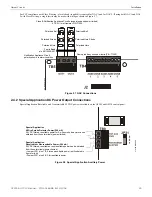
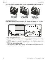
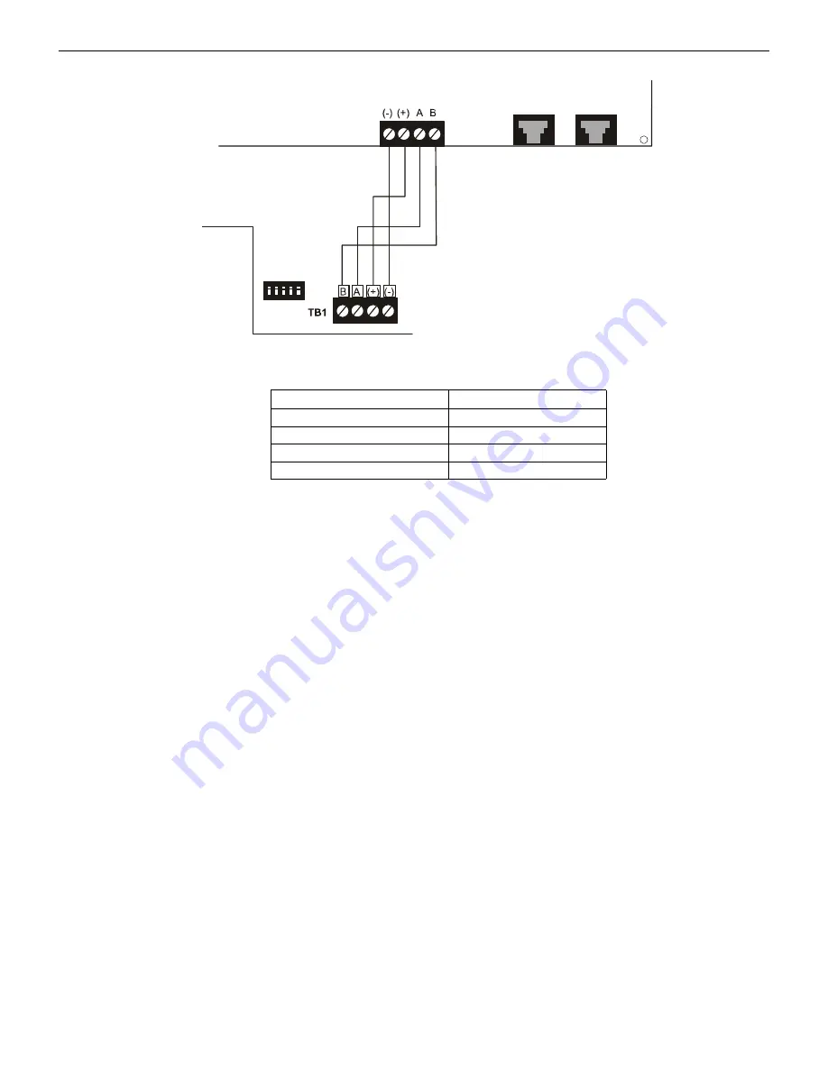
The following table shows the GFANN-80 connections to the GF505/GF510.
Programming
Following installation and wiring of the GFANN-80 LCD annunciator to the FACP, the annunciator must be added to the system via
FACP programming. Refer to the programming section titled “ANN-BUS” on page 63 in this manual for detailed programming informa-
tion. Select the LCD option for programming.
2.8.4 GFANN-LED Annunciator Module
The GFANN-LED annunciator module provides LED annunciation of general system faults and input zones when used with a compati-
ble FACP. The GFANN-LED module provides alarm (red), trouble (yellow) and supervisory (yellow) indication for up to ten input
zones.
Specifications
•
Max. ANN-BUS Voltage: 24 VDC
•
Max. Current:
Alarm: 68 mA
Standby: 28 mA
•
Operating Temperature: 32
o
F to 120
o
F (0
o
C to 49
o
C)
•
For indoor use in a dry location only
Mounting/Installation
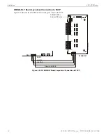
Install the GFANN-LED Module as described in the documentation supplied with the annunciator.
GF505/GF510 (TB3)
GFANN-80 (TB1)
Terminal 4 GND (-)
Terminal 1 (-)
Terminal 3 PWR (+)
Terminal 2 (+)
Terminal 2 A (ANN-BUS)
Terminal 3 (A)
Terminal 1 B (ANN-BUS)
Terminal 4 (B)
Figure 2.22 GFANN-80 Wiring to FACP
FACP
GFANN-80
ANN-BUS and power wiring are
supervised and power-limited
4 3 2 1
TB3
Primary ANN-BUS
an
n8
0to
5x.
wm
f
GF505 & GF510 Manual —
P/N 53164:B5 6/12/2018
39

