Programming
Master Programming Level
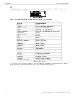
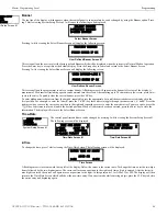
Note that in the two preceding screens, an arrow appears to inform the programmer that additional options can be viewed by pressing the
keypad
down
arrow key.
3.5 Master Programming Level
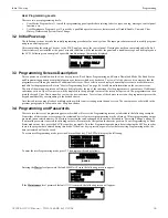
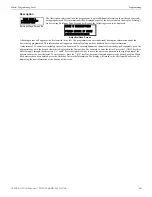
When the Master Program Level password is entered, the control panel will enter user Programming mode. In this mode, the piezo
sounder remains off, the trouble relay is activated and the system Trouble LED flashes until Programming mode is exited. The following
display will appear:
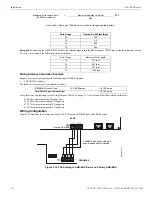
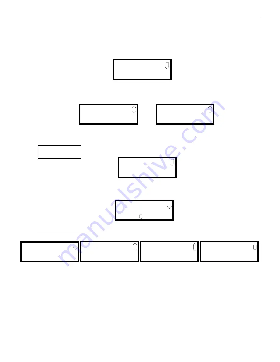
The down arrow which appears in the display indicates that additional programming choices can be viewed by pressing the down arrow
key on the keypad. If a down and up arrow appear in the display, pressing the ‘down’ arrow key will display the subsequent Program-
ming Screens as illustrated below while pressing the ‘up’ arrow key will display the previous screen.
3.5.1 Input Zones
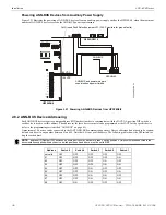
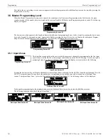
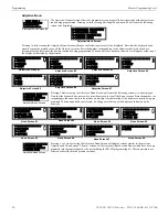
The Input Zones option allows the user to initially program or change the programming for the five input
zones (circuits) on the GF505 or the ten input zones (circuits) on the GF510. Pressing
1
, while viewing Pro-
gramming Screen #1, will select the Input Zones option and display a screen similar to the following:
Pressing the down arrow key will display additional screens for Input Zones 4 through 5 in the GF505 or Input Zones 4 through 10 in the
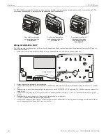
GF510. To program a specific zone, press the number key corresponding to the desired zone while viewing one of the Input Zone
screens. To program Input Zone 1, press the
1
key while viewing Input Zone Screen #1. The following screens will be displayed:
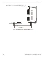
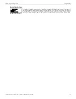
To change the programming for the displayed zone, press the keyboard ‘down’ arrow key to view the Edit Zone screens.
The following examples show the editing of Input Zone 1:
PROGRAMMING
1=INPUT ZONES
2=NACS
3=RELAYS
Programming Screen #1
PROGRAMMING
1=SYSTEM SETUP
2=OPTION MODULES
3=HISTORY
PROGRAMMING
1=WALKTEST
2=CLEAR PROGRAM
3=PASSWORD CHANGE
Programming Screen #2
Programming Screen #3
PROGRAMMING
1=INPUT ZONES
2=NACS
3=RELAYS
Programming Screen #1
INPUT ZONES
1=ZONE 1
2=ZONE 2
3=ZONE 3
Input Zone Screen #1
PULL STATION
ZONE 1
PRESS TO EDIT
Edit Input Zone Screen #1
INPUT ZONE 1
1=ENABLED YES
2=TYPE PULL STATION
3=VERIFICATION NO
Edit Input Zone Screen #2
INPUT ZONE 1
1=PAS/PRE-SIG DELAY
NO DELAY
Edit Input Zone Screen #3
Edit Input Zone Screen #5
INPUT ZONE 1
1=ADJECTIVE/NOUN
2=DESCRIPTION
INPUT ZONE 1
1=FREEZE SUPV. NO
2=ACC MSG#
2
Edit Input Zone Screen #4
46
GF505 & GF510 Manual —
P/N
53164
:B5 6/12/2018


