GW-1000-WE / GW-1000-NWE GATEWAY
31-00425 | Rev.10-20
Part Number: 32348979-001
4
Extended Terminal Cover
Extended Terminal Covers are used for protecting the
Gateway terminals from being tampered and avoid human
contact when the Gateway is mounted on a wall/door.
These covers must be purchased separately.
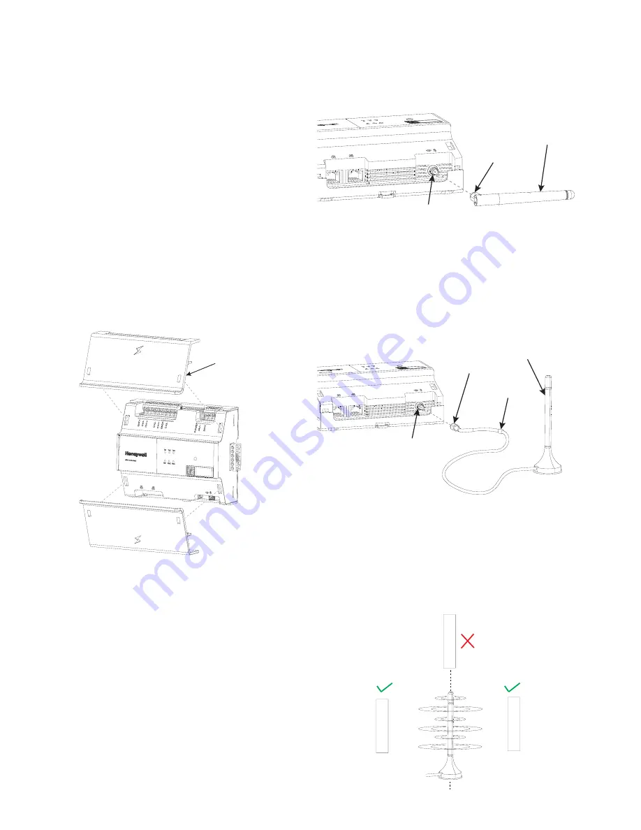
Mounting Extended Terminal Covers
NOTE: The Extended Terminal Covers must be installed
only after completing the terminal wiring and the
antenna installation.
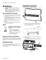
1.
Place the upper Extended Terminal Cover on the top
side of the Gateway so that the rectangular slots of
the Gateway and the rectangular clip of the Extended
Terminal Cover are aligned.
2.
Push the Extended Terminal Cover using both hands
until the cover firmly attached to the Gateway.
3.
Repeat the step above to mount the lower Extended
Terminal Cover.
NOTE: To remove the Extended Terminal Cover, a flat
blade screwdriver is required. See the “Removing
Extended Terminal Covers” section for details.
Antenna
The connected devices can communicate with the Gateway
via Wi-Fi or Bluetooth connections. The Gateway kit
contains a Remote antenna that must be installed
manually on the Gateway. The Remote antenna has a cable
that connects to the Gateway, and the antenna is mounted
outside the panel/cabinet.
The Local antenna can be purchased separately, and it
mounts directly on the Gateway. The Local Antenna is only
used when the Gateway is wall mounted or mounted
outside of a panel/cabinet.
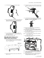
Installing the Local Antenna
1.
Insert the antenna terminal end into the SMA con
-
nector.
2.
Tighten the antenna terminal nut by turning the nut
clockwise. Do not over tighten.
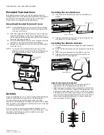
Installing the Remote Antenna
1.
Place the Remote antenna where the signal reception
is good.
2.
Route the Remote antenna wire terminal to the Gate
-
way.
3.
Insert the wire terminal into the SMA connector.
4.
Tighten the wire terminal nut by turning the nut
clockwise. Do not overtighten.
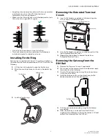
REMOTE ANTENNA PLACEMENT
• Place and align the antenna in a way that the Wi-Fi
signal does not interfere with many obstacles.
• Obstacles such as metal, steel-reinforced concrete wall
filter ~10-90% of the Wi-Fi signal. Other obstacles such
as drywall, wood, glass filter ~0-10% of the Wi-Fi signal.
• The antenna has a strong signal transmission/reception
from the side. See the figure below. Position the sides of
the antenna towards the device it is communicating
with (e.g Smart IO/WiFi Node).
Extended Terminal
Cover
RS485
GND2
CH3+
FGND
-
Local Antenna
SMA Connector
Antenna Terminal
-NWE
SMA Connector
Remote Antenna
Wire Terminal
Ferrite
Ring
Smar
t IO/W
i-F
i Node
Smar
t IO/W
i-F
i Node
Smar
t IO/W
i-F
i Node


