GX-Series Control Panel Installation and Setup Guide
6-41
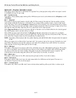
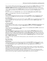
2=Bell Delay
This option is either enabled or disabled. When enabled, it will hold off the start of any bell delay time
programmed in parameter
03
, until the end of the abort time programmed above.
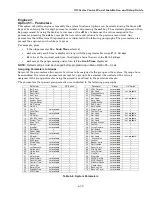
04 = Exit Time
This parameter determines the time allowed to leave the premises via the exit route before the system sets
(arms). The
Exit Time
is programmable within the range
0–300
seconds; the default is
120
seconds.
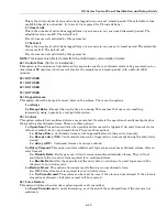
Infinite Exit Time
Assigning a value of 000 seconds sets the
Exit Time
to infinity; an Exit terminator activation (
Final
or
Push-set
zone) is required to complete the setting (arming) of the system. The infinite
Exit Time
is
normally used with a
Push-set
zone to terminate the setting (arming) and an
Entry
zone to start the
unsetting (disarming) procedure.
NOTE: If the system is programmed to Autoset and the Exit Time is programmed to 000, the Exit Time will be
set to 60 seconds for the Autoset — there is no requirement for a Push-Set zone to be activated.
Setting (Arming) Multiple Groups
This parameter can be assigned a different value for each group. If more than one is group is being set
(armed), the longest exit time is adopted for all setting (arming) groups.
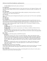
05 = Entry Time
This parameter determines the entry time allowed to users when unsetting (disarming) the system. The
Entry Time
is programmable within the range
0–300
seconds; the default is
45
. Assigning a value of 000
seconds sets the
Entry Time
to infinity.
This parameter can be assigned a different value for each group.
NOTE: A Final zone assigned a * when programming the function will double the programmed Entry Time for the
group to which it is allocated.
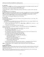
06 = System Reset
This option allows the engineer or the remote code to determine the type that can reset the system following
an intruder alarm. The default type is
3.6
— manager; the programmable range is:
•
2.3–2.5
for the user
•
3.6
for the manager
•
3.7
for the engineer
This parameter can be assigned a different value for each group.
NOTE: This option is affected by reduced resets, menu option (51.55.3).
The panel only requests Engineer Level Reset if alarms have been signaled, via the Communication Module
and appropriate type reset is set to 3.7. If no signal is transmitted, the reset will automatically reduce to
type 3.6. This feature is only active when the DTMF signaling format is selected.
NOTE: This option can also be programmed from parameter 65 = Reset Levels.
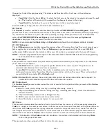
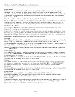
07 = Tamper Reset
This option allows the engineer or the remote code to determine the code type that can reset the system
following a tamper. The default type is
3.7
— engineer; the programmable range is:
•
2.3–2.5
for the user
•
3.6
for the manager
•
3.7
for the engineer
This parameter can be assigned a different value for each group.
NOTE: This option is affected by reduced resets, menu option (51.55.3).
Summary of Contents for GX-48
Page 2: ......
Page 6: ...GX Series Control Panel Installation and Setup Guide iv ...
Page 26: ...GX Series Control Panel Installation and Setup Guide 2 18 ...
Page 32: ...GX Series Control Panel Installation and Setup Guide 3 6 ...
Page 40: ...GX Series Control Panel Installation and Setup Guide 4 8 ...
Page 46: ...GX Series Control Panel Installation and Setup Guide 5 6 ...
Page 184: ...GX Series Control Panel Installation and Setup Guide A 4 ...
Page 194: ...GX Series Control Panel Installation and Setup Guide C 2 ...
Page 200: ...GX Series Control Panel Installation and Setup Guide D 6 ...
Page 204: ...GX Series Control Panel Installation and Setup Guide F 2 ...
Page 207: ......


