HA20 2-Channel Controller
HA20 Technical Manual
2-7
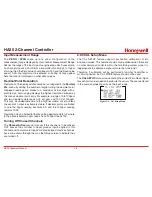
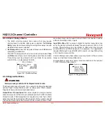
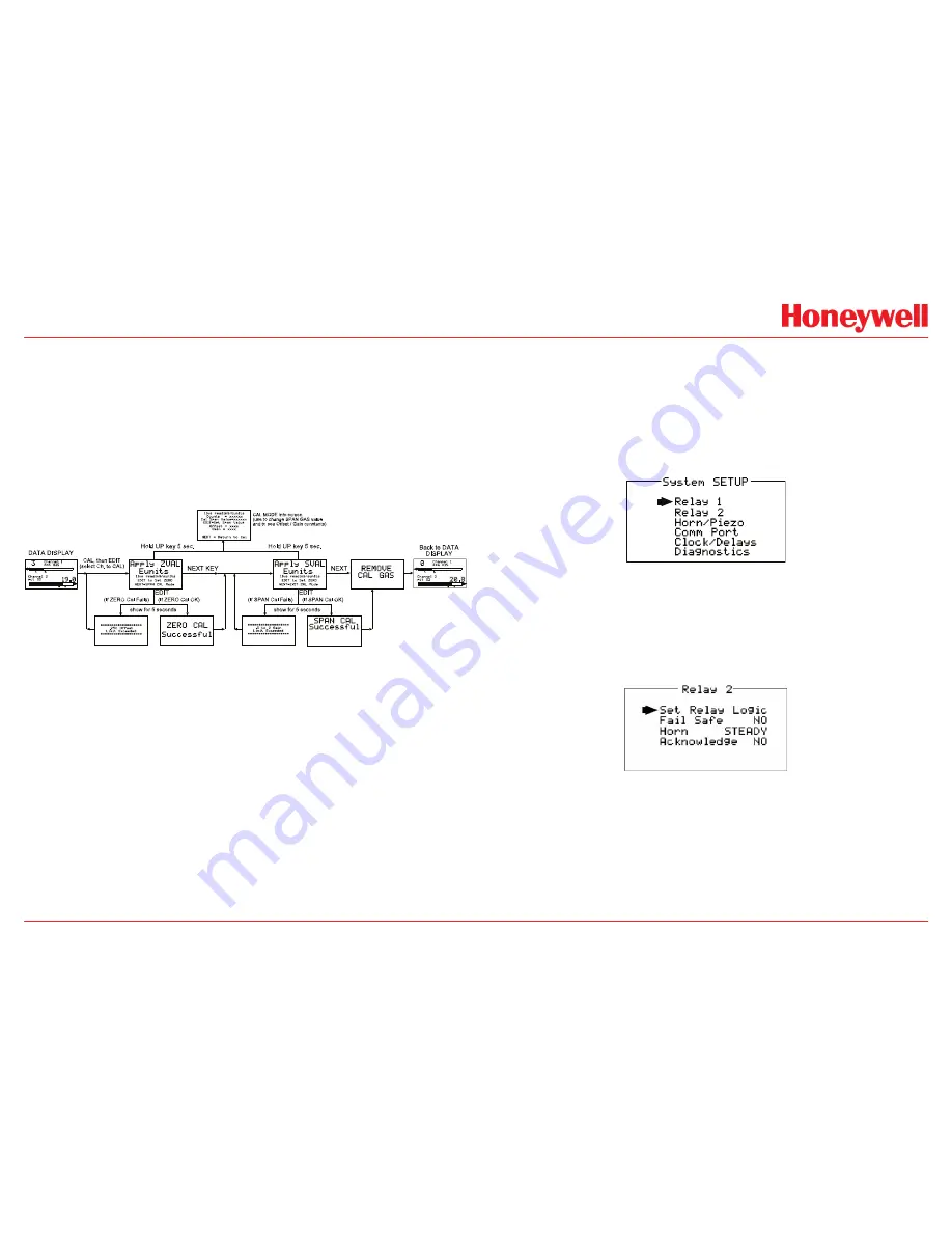
The flow chart in Figure 2-7 illustrates the above procedure. up arrow,
CAL, Next & Edit labels indicate keystrokes (down arrow/CAL is a dual
purpose key). The CAL MODE information screen (top of the chart) is
available for advanced users to see Offset / Gain calibration constants
and live analog to digital converter (A/D) counts. Span Gas calibration
values may also be edited from this screen. Holding the up arrow key
for 5 seconds during CAL MODE displays this screen.
Unity Gain may be used at anytime to cancel incorrect calibrations
and start again.
Figure 2-7. Cal Mode Flow Chart
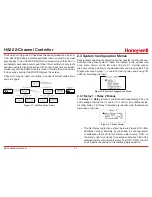
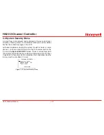
2.3 System Configuration Menus
Several items needing configuration are not specific to either channel
but affect the entire system. These are located in the system tree
entry menu shown on the left side of Figure 2-1. System menus
are accessed by pointing to the desired item and pressing Edit. The
Diagnostics menu group (
\
) is useful for testing relay and analog I/O
without stimulating the input.
Figure 2-8. System Configuration Menu
2.3.1 Relay 1 / Relay 2 Menus
The
Relay 1
&
Relay 2
menus are identical except Relay 2 has an
acknowledge feature that is useful if it controls an audible device.
All other Relay 1 & Relay 2 features are identical and therefore are
discussed only once.
Figure 2-9. Relay Menus
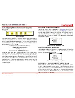
• The Set Relay Logic menu shown below in Figure 2-10 offers
additional “voting” flexibility by controlling the channel alarm
combinations that will trip this common alarm relay. “OVR” on
the menu’s right side stands for override and means ANY of the
selected alarms will activate the relay. The “OR” / “AND” columns
work together based upon the following logic equation:
Summary of Contents for HA20
Page 6: ...HA20 2 Channel Controller HA20 Technical Manual v ...
Page 7: ...HA20 2 Channel Controller HA20 Technical Manual 1 1 1 General Description ...
Page 12: ...HA20 2 Channel Controller HA20 Technical Manual 2 1 2 Operation ...
Page 22: ...HA20 2 Channel Controller HA20 Technical Manual 3 1 3 Motherboard Interface PCB ...
Page 30: ...HA20 2 Channel Controller HA20 Technical Manual 3 9 ...
Page 31: ...HA20 2 Channel Controller HA20 Technical Manual 3 10 ...
Page 32: ...HA20 2 Channel Controller HA20 Technical Manual 4 1 4 Enclosures ...
Page 35: ...HA40 4 Channel Controller HA40 Technical Manual 5 1 5 Parts List ...
Page 37: ...HA20 2 Channel Controller HA20 Technical Manual 6 1 6 Specifications ...
Page 39: ...HA20 2 Channel Controller HA20 Technical Manual 7 1 7 Warranty ...


