background image

HA20 2-Channel Controller

HA20 Technical Manual

3-2

3 Motherboard Interface PCB

(P/N 10-0215)

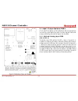
The HA20 Motherboard shown in Figure 3.2 is the interface between 
the Display / CPU assembly and all other system I/O devices. The 
Display / CPU assembly attaches to the motherboard with 4-standoffs 
and connects via ribbon cable to S1. Several input options, described 
in the following sections, are available that may be installed into the 
Sensor Input Option P1 connector located on the lower left side of 
the motherboard. The middle position P2 connector is for the 10-0223 
4-20mA Output option and the right position P3 connector is for the 
10-0222 Discrete Relay option. Other option devices such as Modbus 
RTU RS-485, Ethernet and a data logger may also be installed to 
connectors located on the Motherboard.

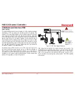
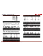
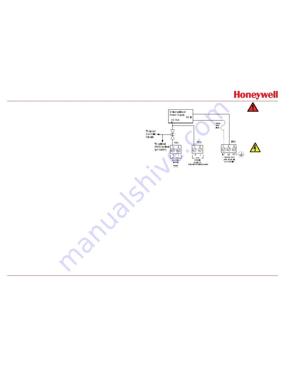
The  Motherboard  PCB  contains  a  24 VDC  universal  input  (100-
240 VAC)  switching  power  supply  with  up  to  350mA  available  at 
TB3  Auxiliary  Power  Output  terminals  (Figure  3.1).  If  AC  power  is 
unavailable, or if a DC battery back-up supply is needed, TB1 provides 
terminals  for  DC  power  input.  Blocking  diodes  isolate  internal  and 
external DC supplies as shown in Figure 3-1.

2 Amp, 250V, 5x20mm fuse located under

terminal cover.

WARNING

: For continued protection against

fire replace only with same type and rating of fuse.

Universal Input 

Power Supply

AC In

DC Out

+

To Local 

Controller 

Circuits

+      -

+      -

L1    L2   GND

TB1

TB3

TB5

D C  PW R

SU PPLY

IN PU T

A U X

POW ER

OU TPU T

100 -240  VA C

. 45A  50 60  H z

A C  POW ER

SHOCK HAZARD

RISK OF ELECTRICAL

SHOCK - DISCONNECT OR

TURN OFF POWER

BEFORE SERVICING THE

EQUIPMENT

2-Amp

250V

Fuse

To optional 

24VDC terminals

(p/n 10-0221)

(only with AC primary power)

Figure 3-1. DC Power Supply Schematic

TB2  offers  field  terminals  for  a  remote  alarm  reset  switch. The 
motherboard also includes alarm relays 1 & 2 (K1 & K2) and their 
indicating LED’s. TB4 provides field wiring terminals for these relays. 
TB5  is  for  connection  to  the  85-240 VAC  power  source.  J2  is  a 
2-pin connector for powering the optional part # 1000-1892 audible 
annunciator.

Summary of Contents for HA20

Page 1: ...tic Keypad Keypad buttons behind door HA20 Display Alarm Controller Two Channel Edit Alarm Reset Next 219995 Classified to CSA C22 2 NO 152 for combustibles detection Class I DIV 2 Groups A B C D READ UNDERSTAND MANUAL S N 90 or 10 30 VDC 3 WATTS Power 100 240 V 50 60 Hz 45 A Channel 2 Cal ...

Page 2: ...f this instrument have been assessed by CSA for 122 2 No 152 performance requirements for combustibles using mA input This equipment is suitable for use in Class I Division 2 Groups A B C and D or non hazardous locations only EXPLOSION HAZARD SUBSTITUTION OF COMPONENTS MAY IMPAIR SUITABILITY FOR CLASS I DIVISION 2 EXPLOSION HAZARD DO NOT REPLACE FUSE UNLESS POWER HAS BEEN SWITCHED OFF OR THE AREA ...

Page 3: ...1 3 Warning 1 4 1 3 2 Relays 1 4 1 3 3 Ambient Temperature Range 1 4 1 3 4 Humidity Range 1 4 1 3 5 Altitude 1 4 1 3 6 Housings Installation Categories 1 5 1 3 7 Approvals 1 5 2 Operation 2 Operation 2 2 2 1 Setup Menu Configuration 2 2 2 2 Changing Menu Variables Using The Keypad 2 3 2 2 1 Setup Configuration Menus 2 3 2 2 2 Channel Setup Entry Menu 2 3 2 2 3 Alarm 1 Alarm 2 Alarm 3 Set Up Menus ...

Page 4: ... 2 4 System Security Menu 2 10 3 Motherboard Interface PCB 3 Motherboard Interface PCB 3 2 3 1 Input Output Optional PCB s 3 3 3 1 1 Optional Analog Input PCB 3 3 3 1 2 Optional Discrete Relay PCB s 3 4 3 1 3 Optional 4 20mA Analog Output Board 3 5 3 2 Modbus RS 232 RS 485 Interface Option 3 6 3 2 1 Modbus Register And Function Code Summary 3 7 4 Enclosures 4 Enclosures 4 2 4 1 HA20PCS HA20SS NEMA...

Page 5: ...HA20 2 Channel Controller HA20 Technical Manual iv 5 Specifications 6 2 7 Warranty Honeywell Analytics Warranty Statement 7 2 ...

Page 6: ...HA20 2 Channel Controller HA20 Technical Manual v ...

Page 7: ...HA20 2 Channel Controller HA20 Technical Manual 1 1 1 General Description ...

Page 8: ...ic LCD readout displays monitored data as bar graphs 30 minute trends and engineering units System configuration is via user friendly menus and all configuration data is retained in non volatile memory during power interruptions The HA20 front panel shown in Figure 1 1 displays the bar graph data screen The five button symbols below the display are magnetically activated using the magnetic wand su...

Page 9: ...nel as shown in Figure 1 3 Use the Next key to scroll between data screens 1 1 3 Blind Mode Screen The HA20 Blind Mode screen Figure 1 3 does not allow viewing of channel engineering unit values It only indicates the system s alarm status and time date Some applications require only alarm status be displayed and prefer monitored values not be shown A SECURITY menu see Section 2 4 allows locking al...

Page 10: ...ction 5 Specifications WARNING A backup or external DC power source DOES NOT source auxiliary power output see figure 3 1 TB3 1 3 2 Relays Two mechanical dry contact Common Form C relays are standard and may be mapped to various alarm events as described in Section 2 3 1 HA20 s may also be equipped with optional solid state common Form A relays see Section 5 Specifications for details in applicati...

Page 11: ...teel SS316 NEMA4X Polycarbonate NEMA4X NEMA 7 wall mount for DIV 1 2 Groups B C D includes O ring in door to satisfy NEMA 4 rating Includes standard non intrusive magnetic keypad 1 3 7 Approvals CSA C22 2 No 1010 1 and ISA S82 02 CSA C22 2 No 152 for combustibles mA input only UL 1604 C22 2 No 213 Div 2 Groups A B C D EN55011 EN61000 CE Mark CSA File 219995 and may be seen at www CSA International...

Page 12: ...HA20 2 Channel Controller HA20 Technical Manual 2 1 2 Operation ...

Page 13: ...ring with HA20 parameters A sign on screen appears briefly after power is applied that indicates what type of input output options are configured with the unit Several signal conditioning input options are available to allow the HA20 to accept sensor and other analog signals directly see Section 3 1 2 1 Setup Menu Configuration Variables within the CHANNEL see Section 2 2 and SYSTEM see Section 2 ...

Page 14: ...ns the LCD to the data display 2 2 1 Setup Configuration Menus The SETUP menu shown in the middle of Figure 2 1 and in Figure 2 2 is reached by pressing Edit with any data display present This is the entry level screen to all Channel System and Security menus It also shows the firmware version operating in the HA20 Use the up down arrows keys to move the pointer to the desired menu and press the E...

Page 15: ...l LED and optional discrete relay to latch NO allows all outputs for this alarm to automatically reset after the alarm condition clears Discrete LED indicators on the front panel indicate the status of each alarm Any new alarm event causes the associated LED to flash until an Alarm Reset occurs causing an acknowledged steady on condition Operators should recognize new alarms by a flashing LED Alar...

Page 16: ...o unless the sensor s output is extremely stable If decimal points are limited to one the 0ppm reading becomes 0 0 and the 100ppm reading remains 100 0 Resolution may be limited further by setting decimal points to 0 where in the above example 0ppm reads 0 and 100ppm reads 100 Turning Off Unused Channels The Channel Active menu entry asks if this channel is to be utilized OFF causes the controller...

Page 17: ...iration date Calibrate a new sensor before use Allow the sensor to stabilize before starting calibration Consult the appropriate sensor manual for warm up times Calibrate on a regular schedule Consult the appropriate sensor manual for calibration intervals or depending on use and sensor exposure to poisons and contaminants Calibrate only in a clean atmosphere free of background gas Use the followi...

Page 18: ...he entire system These are located in the system tree entry menu shown on the left side of Figure 2 1 System menus are accessed by pointing to the desired item and pressing Edit The Diagnostics menu group is useful for testing relay and analog I O without stimulating the input Figure 2 8 System Configuration Menu 2 3 1 Relay 1 Relay 2 Menus The Relay 1 Relay 2 menus are identical except Relay 2 ha...

Page 19: ...device is being driven by the relay The acknowledge feature is not available for Relay 1 since it is often used for driving a warning light and Relay 2 for driving a horn Using Acknowledge thus deactivating when horn and light are activated could be dangerous since this deactivates both and no indication of the High alarm remains 2 3 2 Horn Piezo Menu The HA20 display PCB is equipped with a small ...

Page 20: ...tic menu items are described below Output Zero Output Span DAC value digital to analog converter menu items are set at the factory to calibrate optional 10 0223 4 20mA Output boards If field adjustment is required monitor the 4 20mA output and set the Output Zero DAC value for 4mA on each channel then set the Output Span DAC value for 20mA on each channel These menu items may also be used to drive...

Page 21: ...ssage on the LCD Authorized individuals locking the system should first enter a name phone or other contact information in the 12 character field on the top line of the System SECURITY screen To lock or unlock the system the correct 4 digit authorization number must be entered into the Pass Code field It is very important to remember the 4 digit code since the factory must be consulted if it is lo...

Page 22: ...HA20 2 Channel Controller HA20 Technical Manual 3 1 3 Motherboard Interface PCB ...

Page 23: ...t TB3 Auxiliary Power Output terminals Figure 3 1 If AC power is unavailable or if a DC battery back up supply is needed TB1 provides terminals for DC power input Blocking diodes isolate internal and external DC supplies as shown in Figure 3 1 2 Amp 250V 5x20mm fuse located under terminal cover WARNING For continued protection against fire replace only with same type and rating of fuse Universal I...

Page 24: ...for correct shielding of incoming signals TB2 Dry contact input for use with optional remote Alarm Reset switch Wires must be shorter than 10 feet shielded if longer than 2 feet TB1 Available for 24 VDC primary power input May also be used as battery back up to AC primary power source TIE TB5 GND to EARTH J3 SHOCK HAZARD RISK OF ELECTRICAL SHOCK DISCONNECT OR TURN OFF POWER BEFORE SERVICING THE EQ...

Page 25: ...ignal TB2 1or2 TB1 1 Ch1 TB1 3 Ch2 Figure 3 4 Wiring for 2 and 3 wire Transmitters 3 1 2 Optional Discrete Relay PCB s P N 10 0222 The optional Discrete Relay PCB shown in Figure 3 6 adds six 5 amp form C relays Each relay is associated to either A1 A2 or A3 for channel 1 or 2 Many HA20 applications utilize the standard equipped Relay 1 Relay 2 see Section 2 3 1 and do not require optional discret...

Page 26: ...for 100 readings Make certain that the mA loop output is set to LATCHING on reading devices connected to the HA40 If the HA20 primary power is 100 240 VAC 4 20mA outputs are capable of driving 20mA through a 750 ohm load Outputs are self powered and DC power should not be provided by the receiving device Precision calibration of the 4 20mA output DAC digital to analog converter is accomplished via...

Page 27: ...oard TB1 provides two pairs of T Rx terminals and a floating terminal for shield continuation This makes it easy to multi drop HA20s onto an RS 485 cable without doubling wires into the same screw terminals RS 232 interface may be made by connecting to DB9 connector S1 Section 3 2 1 lists all modbus registers and their function codes WARNING Follow correct IEEE RS 232 and RS 485 installation guide...

Page 28: ...0 bit value representing the A2D value of 0 to 1023 for 25 to 103 FS 197 0 1003 100 D2A Chan 1 31003 4 NA D2A Chan 2 31004 4 NA 10 bit value representing the D2A value of 0 to 1023 after all cal features are applied Chan 1 Status 31005 4 NA Chan 2 Status 31006 4 NA 16 bit status word bit assignment for each channel ALARM1_BELOW_BIT ALARM2_BELOW_BIT ALARM3_BELOW_BIT ALARM1_LATCH_BIT ALARM2_LATCH_BI...

Page 29: ... Chan 1 Span Real 41003 4 NA Chan 1 Span Devisor 41004 4 NA Chan 1 Alarm 1 Real 41005 4 NA Chan 1 Alarm 1 Devisor 41006 4 NA Chan 1 Alarm 2 Real 41007 4 NA Chan 1 Alarm 2 Devisor 41008 4 NA Chan 1 Alarm 3 Real 41009 4 NA Binary Cal Data Chan 1 A2D MIN 41021 4 NA Chan 1 A2D MAX 41022 4 NA Chan 1 D2A MIN 41023 4 NA Chan 1 D2A MAX 41024 4 NA Chan 2 A2D MIN 41025 4 NA Chan 2 A2D MAX 41026 4 NA Chan 2 ...

Page 30: ...HA20 2 Channel Controller HA20 Technical Manual 3 9 ...

Page 31: ...HA20 2 Channel Controller HA20 Technical Manual 3 10 ...

Page 32: ...HA20 2 Channel Controller HA20 Technical Manual 4 1 4 Enclosures ...

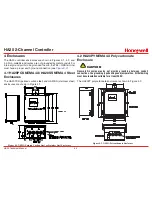
Page 33: ...0 4 12 5 84 7 56 2 70 6 20 11 81 12 90 13 65 C L 2 56 8 84 9 84 1 2 in NPTConduit Fittings Typical 4 places Single 1 4 Turn Latch Instrument Viewing Window Notes Part 1000 2377 316 Stainless Steel Part 1000 2378 Painted Carbon Steel Side View Front View Bottom View Material Figure 4 1 NEMA Painted Carbon Steel or Stainless Steel Enclosure 4 2 HA20PY NEMA 4X Polycarbonate Enclosure CAUTION Nonmetal...

Page 34: ...l 4 3 4 3 HA20XP NEMA 7 Explosion Proof Wall Mount Enclosure The HA20XP enclosure shown in Figure 4 3 is an aluminum NEMA 7 wall mount enclosure designed for use in potentially hazardous areas Figure 4 3 NEMA 7 Explosion Proof Wall Mount Enclosure ...

Page 35: ...HA40 4 Channel Controller HA40 Technical Manual 5 1 5 Parts List ...

Page 36: ...Magnetic Keypad for nonintrusive control 4 20mA I O Options 10 0221 2 Dual 4 20mA Analog INPUT PCB 10 0223 Dual 4 20mA Analog OUTPUT PCB Options and Accessories 10 0222 Relay Option to add six 5 amp Form C relays 10 0227 Modbus RS 232 RS 485 Option 10 0284 Division 2 red xenon strobe light includes mounting to top of NEMA 4 models 1000 1892 100db piezo audible NEMA 4X enclosure only ...

Page 37: ...HA20 2 Channel Controller HA20 Technical Manual 6 1 6 Specifications ...

Page 38: ...122ºF Operating humidity range 0 to 90 RH non condensing Operating altitude 2000m 6562 ft Audible alarm 100 dB Display 128 x 64 backlight graphic LCD Visual Indicators 6 LED status indicators Pollution degree N4 3 Enclosure N4 NEMA 4X Div 2 Groups A B C D Category II Enclosure XP NEMA 7 Div 1 2 Groups B C D Enclosure NEMA 4 painted carbon steel Enclosure NEMA 4X SS316 Enclosure NEMA 4X Polycarbona...

Page 39: ...HA20 2 Channel Controller HA20 Technical Manual 7 1 7 Warranty ...

Page 40: ...se warranty terms Time and travel expenses for on site warranty services will be charged at Honeywell Analytics normal billing rates Contact your Honeywell Analytics representative for information on available Service Contracts Honeywell Analytics shall not be liable for any loss or damage whatsoever or howsoever occasioned which may be a direct or indirect result of the use or operation of the Co...

Page 41: ...etection honeywell com Europe Middle Easst and Africa ha global service honeywell com www honeywell com Asia Pacific Honeywell Analytics 508 Kolon Science Valley l 187 10 Guro Dong Guro Gu Seoul 152 050 Korea Tel 82 2 2025 0300 Fax 82 2 2025 029 anapitics ap honeywell com Please Note While every effort has been made to ensure accuracy in this publication no responsibility can be accepted for error...

Reviews: