background image

18

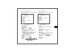
5.8.3.1 MD area selection

Select AREA SEL. and press + or – button to enter 
submenu. It will show as in Fig.5-12.

<< MD ZONE SETUP >>

ZONE 

1

FUNCTION 

OFF

SIZE SET
SAVE & EXIT
RETURN

<Fig.5-12 MD Zone Setup>

MD Zone setting

This zone is effective when MD DISPLAY is FRAME.

ZONE 

1 ~ 4

Function setting

FUNCTION 

OFF 

ON

MD frame size setting

Press + or – button to set MD frame size and position.
- set the MD frame size using direction buttons

(+,-,UP,DOWN)

- press MENU button in order to change the position.
- set the MD frame position using direction buttons.
- press the MENU button and hold for more than 

2 seconds to exit size and position setting menu.

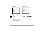
5.8.4 Communication setting

In order to use remote control through RS-485, set the 
values properly.

<< COMMUNICATION SETUP >>

CAMERA ID 

1

BAUDRATE 

9600

PROTOCOL 

DEFAULT

SAVE & EXIT
RETURN

<Fig.5-13 Comm. Setup>

Camera ID setting

CAMERA ID 

0 ~ 255

Baudrate setting

BAUDRATE                    2400 

4800 

9600 

19200

38400 

57600

Protocol setting

PROTOCOL          DEFAULT 

PELCO 

KD6 

VCL

Summary of Contents for HCC-960 Series

Page 1: ...C 960 965 Series READ AND KEEP THIS OPERATION MANUAL The exclamation point within an equilateral triangle is intended to alert the user to the presence of important operating and maintenance servicing instructions in the literature accompanying the appliance ...

Page 2: ...planation of Graphical Symbols This symbol is intended to alert the user to the presence of uninsulated dangerous voltage within the product s enclosure that may be of sufficient magnitude to constitute a risk of electric shock to persons This symbol is intended to alert the user to the presence of important operating and maintenance Servicing Instructions in the literature accompanying the applia...

Page 3: ...convenience receptacles and the point where they exit from the apparatus 11 Only use attachments accessories specified by the manufacturer 12 Use only with a cart stand tripod bracket or table specified by the manufacturer or sold with the apparatus When a can is used use caution when moving the cart apparatus combination to avoid injury from tip over 13 Unplug this apparatus during lighting storm...

Page 4: ...iately turn the power off then contact your supplier 9 Cleaning Turn the power off and wipe off the dirt with a dry soft cloth If it is extremely dirty use furniture cleaner to wipe it off To clean the lens use a blower or lens cleaning tissue available from any camera dealer 10 Do not shoot any source of bright light If the objects contain very bright areas bright vertical or horizontal lines may...

Page 5: ...een Display 12 6 Specifications 20 7 Dimensions 22 Thank you for using this High Resolution Camera with WDR To get the best efficiency read carefully all instructions in this manual before use and keep this manual for reference If you have any problems with this camera contact your supplier to service ...

Page 6: ... Excellent DNR Digital Noise Reduction function 2D NR 3D NR PZM Privacy Zone Masking of selected views for privacy protection Digital Zoom function max x256 Adapted adjustable C CS mount Excellent signal to noise ratio of more than 50dB 2 WAY Auto Iris Both Video iris or DC iris lens can be used Auto White Balance Auto white balance realizes true color reproduction within various light sources OSD...

Page 7: ...ions C CS Mount Adaptor C Mount lens Turn Counterclockwise CS Mount lens Turn Clockwise Set Screw Loosen Locking Ring with a Phillips screwdriver to adjust Mounting Ring Lens Connector Connect Auto Iris Lens plug 7 ...

Page 8: ...BUTTON DOWN BUTTON BUTTON CAMERA CONTROL CONNECTOR VIDEO OUTPUT LENS TYPE SELECT SWITCH POWER ON LAMP DC Lens with no iris amp VSD Lens with iris amp POWER INPUT TERMINAL HCC 960 Ser DC12V MODEL HCC 965 Ser AC24V DC12V MODEL POWER INPUT TERMINAL DC12V AC24V or DC12V ...

Page 9: ...w with a Phillips screwdriver Turn the mount ring counterclockwise in case of C Mount Lens Turn the mount ring clockwise in case of CS Mount Lens 3 2 2 Auto Iris Lens Remove the cover of the iris lens plug and connect with Lens cable VSD LENS PIN CONFIGURATION 1 2 3 4 1 POWER 12V 2 NO CONNECTION 3 VIDEO SIGNAL 4 GND Set the select switch to VSD DC IRIS LENS PIN CONFIGURATION 1 2 3 4 1 CONTROL 2 CO...

Page 10: ... infinity b Tune the mount adapter to get a clear picture distance from camera to object is more than 23m and fasten the Set Screw 3 3 2 In case of zoom lens a Loosen the Set Screw and set the lens to the maximum telephoto position Then turn the focus ring to focus in the case of Auto iris lens shoot a comparatively dark object or reduce the ambient light so that the Iris is fully open b Set the l...

Page 11: ...l Connection 11 4 1 RS 485 Connection Serial Cable RS485 Converter 3 4 TRx TRx 4P Cable RS485 Converter TRx TRx RS485 Connect to Serial Port CONT DC 12V AC 24V GND 4P Cable 1 Red NC 2 Blue NC 3 Yellow TRx 4 Black TRx ...

Page 12: ...AC 24V GND UP BUTTON RIGHT BUTTON LEFT BUTTON SETUP BUTTON DOWN BUTTON Display SETUP MENU Press and hold the MENU button for 2 seconds to display the SETUP MENU Press the UP or DOWN button to select a menu item Move from SETUP MENU to submenu Press or button to enter the selected submenu Press the UP or DOWN button to select a menu item If you don t operate any key for 20sec OSD will appears on th...

Page 13: ...1 63 1 120 1 100 1 250 1 10000 ELC brightness adjustment BRIGHTNESS 0 100 Fig 5 2 ELC Setting AE SETUP CONTROL DC SHUTTER 1 63 LEVEL ADJ COMPLETED BRIGHTNESS 40 SAVE EXIT EXIT 5 2 2 ALC mode Lens type select CONTROL DC VSD Shutter speed control This field is not adjustable when the camera is set to AUTO SHUTTER 1 53 1 63 1 120 1 100 1 250 1 10000 Lens level adjustment Adjust level for DC VSD lens ...

Page 14: ...or Rolling less Mode Reduces color rolling under the office environments with fluorescent light WB CONT ATW INDOOR OUTDOOR MANUAL AWC LOCK AWC AUTO CRLS WB SETUP CONTROL AUTO RED 0 BLUE 0 SAVE EXIT EXIT Fig 5 4 WB Setting 5 3 1 ATW In ATW mode change of RED and BLUE value means White shift to reddish or bluish CONTROL AUTO RED 127 127 BLUE 127 127 5 3 2 MANUAL CONTROL R B RED UP STOP BLUE DOWN STO...

Page 15: ...5 BLC Setting Fig 5 6 BLC Area Setting excessive light area 0 the subject area 5 4 2 WDR WDR Wide Dynamic Range is one of Backlight Compensation you can watch not only the object in the center but also the objects around clearly LONG TERM REF 0 255 SHORT TERM REF 0 255 HL COMP 0 63 The higher HL COMP value you can see the bright area clearly LONG TERM REF SHORT TERM REF are the weight of WDR opera...

Page 16: ... level of gain changes 2D NR or 3D NR can decrease digital noise DNR OFF 2D NR 3D NR 2D NR and 3D NR have a submenu you can set the DNR level In case of 2D NR LEVEL 1 6 In case of 3D NR LEVEL 1 31 The higher the level in 3D NR the greater the level of noise is reduced however there will be an increase in the ghost image 5 8 Special Setup SPECIAL SETUP GENERAL SETUP PZM SETUP MD SETUP OFF COMM SETU...

Page 17: ...ze and position setting menu PZM alpha blending setting ALPHA 0 3 Mosaic function setting MOSAIC OFF ON PZM color COLOR BLUE GREEN YELLOW CYAN MAGENTA BLACK D GRAY L GRAY WHITE RED 5 8 3 Motion Detection setting The camera detects an object s movement by sensing disparity of outline MD SETUP AREA SEL SENSITIVITY 128 DISPLAY TRACE BRIGHTNESS 8 SAVE EXIT RETURN Fig 5 11 MD Setup AREA SEL In AREA SEL...

Page 18: ... MD frame size using direction buttons UP DOWN press MENU button in order to change the position set the MD frame position using direction buttons press the MENU button and hold for more than 2 seconds to exit size and position setting menu 5 8 4 Communication setting In order to use remote control through RS 485 set the values properly COMMUNICATION SETUP CAMERA ID 1 BAUDRATE 9600 PROTOCOL DEFAUL...

Page 19: ...oftware Day Night mode setting The NIGHTSHOT SETUP allows to set the camera reaction under low light illumination and switch mode between Day and Night modes AUTO Day and Night modes change by auto detecting luminance ON Night mode OFF Day mode NIGHTSHOT OFF AUTO ON Dwell time setting DWELL 1 30 Day to Night level setting D2N LEVEL 0 10 Night to Day level setting N2D LEVEL 0 10 Burst signal settin...

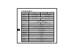
Page 20: ...nation Less than 0 1lx F1 2 50IRE AGC 34dB Less than 0 001lx F1 2 50IRE AGC 34dB 512FLD Electronic Shutter Auto 1 60 100 000sec Manual 8steps Auto 1 50 100 000sec Manual 8steps S N Ratio More than 50dB AGC 6 34dB 7steps White Balance ATW INDOOR OUTDOOR MANUAL AWC LOCK AWC AUTO CRLS BLC OFF BLC ABLC WDR Privacy Zone Masking Max 16 zones Alpha Mosaic Color Digital Noise Reduction OFF 2D NR 3D NR Mot...

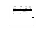
Page 21: ...2V 2V AC24V 10 DC12V 2V Power Consumption Max 2 5W Max 2 5W Max 4W Power Input Terminal Block 3pin Operating Temperature 10 50 Storage Temperature 20 70 Operating Humidity 90 RH non condensing Color Silver Gray Dimension 68 W x 56 H x 118 D mm Weight 360g 360g 390g 21 ...

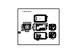
Page 22: ...7 Dimensions CONT DC 12V AC 24V GND CONT DC 12V GND Unit mm HCC 960 Series HCC 965 Series 22 ...

Page 23: ...MEMO Printed in Korea D 100077 REV 0 Honeywell Co Ltd ...

Reviews: