background image

HCE80(R) / HCC80(R)

 Mounting and operation

23

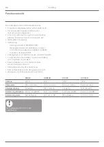
Changing the fuse

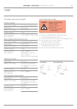
Only use ceramic fuses of the type 
230 V AC; 2.5 A; fast; 5 x 20 mm.

!

1

  Deenergize the device.

2

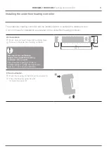
  Open the housing (see "Opening 

the housing" on Page 10).

3

  Remove the holder with the fuse (Steps 1 to 3).

1

4

  Replace the old fuse by a new one.

5

  Insert the fuse again.

6

  Close the housing (see "Closing the 

housing" on Page 13).

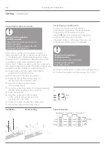
Restoring the factory settings at the 
underfloor heating controller

When the underfloor heating controller 
is reset to the factory settings, the cur-
rent configuration (assignment) is deleted. 
The underfloor heating controller retains 
its configuration after a power failure.

!

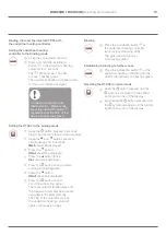
1

  Keep the 

Mode

 and   buttons pressed 

simultaneously for at least 10 seconds.


After 4 seconds the controller changes over 

to test mode. Continue to keep the buttons 

pressed until the   LED flashes orange.


The factory settings have been reset at 

the underfloor heating controller.

Fault displays

If the   LED lights up, a fault is present 

in at least one temperature zone.
The colours of the zone LEDs 1...8 provide information 

on the type of fault in the respective temperature zone:

Status

Meaning

Off

No fault

Flashing red

No connection to the room temperature 

sensor/setpoint adjuster

Flashing 

orange

No connection to the setpoint 

adjuster and 

evohome

 controller 

or CM927 operating device

Flashing green No connection to the 

evohome

 controller 

or the CM927 operating device

The fault display extinguishes as soon 
as the fault has been eliminated.

!

Help with problems

1

2

3

4

Summary of Contents for HCC80

Page 1: ...HCE80 R HCC80 R Mounting and operation Montage en bedrijf Montage et fonctionnement ...

Page 2: ... ii English 1 Nederlands 30 Français 59 ...

Page 3: ...ii 1x 1x 1x 8x 8x 1x 1x 1 3 2 2 2 3 4 5 1 6 7 8 3 45 67 8 Power 1 2 1 2 3 4 5 6 7 8 Mode 14 9 10 Z3 13 12 Z1 Z2 Z4 Z5 Z6 Z7Z8 11 PE L N PE 1 2 3 4 5 6 B H C TW MCR Panter Smile 5 5 mm 5 5 mm 7mm Fig 1 Fig 2 Fig 5 Fig 6 Fig 7 Fig 3 Fig 4 HRA80 ...

Page 4: ... iv ...

Page 5: ...oor heating controller without time program 18 Cancelling the assignment of zones rooms 21 Checking the installation 22 Help with problems 23 Changing the fuse 23 Restoring the factory settings at the underfloor heating controller 23 Fault displays 23 Errors and elimination 24 Options 25 Boiler feedback 25 Allocating relay modules for controlling the heat generator 25 Cooling with CM927 26 Time pr...

Page 6: ...ig 1 Scope of delivery Fig 2 Opening the housing Fig 3 Display and operating elements 1 Power Power supply on off 2 Information display 3 Installation display 4 Mode Operating mode button 5 Installation button 6 Pump off off display 7 1 8 Zone LEDs 8 Labelling of Zones 1 8 Fig 4 Connections 9 I O connector 10 Switch for setting normally open normally closed 11 Slot for expansion module HCS80 12 Co...

Page 7: ...TS92 Measures the room temperature room setpoint temperature can be set with digital display Temperature selector T87RF Measures the room temperature room setpoint temperature can be set with digital display Room setpoint generator sensor HCW82 Measures the room temperature room setpoint temperature can be set using an adjustment dial Room temperature sensor HCF82 Measures the room temperature Und...

Page 8: ...S92A E HCF82 HCW82 Option T87 RF Underfloor heating control system with a central operating device CM927 The central operating device CM927 communicates directly with the underfloor heating controller HCE80 R HCC80 R The room setpoint generators sensors DTS92 T87 RF HCW82 or HCF82 as well as the boiler relay BDR91 also communicate directly with the underfloor heating controller HCE80 R HCC80 R The...

Page 9: ...ng 1 antenna internal or external can be used for 3 controllers Rapid installation through screwless terminals of the thermal actuators Intelligent controlling via fuzzy logic Simple diagnoses of the wireless transmission Operating state display via LEDs HCE80 HCE80R HCC80 HCC80R Antenna External External Internal Internal Pump relay 230 V AC internal 230 V AC internal 230 V AC internal 230 V AC i...

Page 10: ... Number of underfloor heating controllers 8 24 1 16 48 2 24 72 3 Specifying temperature zones 1 Specify the number of zones and the corresponding rooms 2 Allocate the corresponding room device for example HCW82 and the required thermal actuators to each zone 3 Label the room devices and thermal actuators for the respective zone see fold out page Fig 4 Z1 Z8 Explanation of the example The living ar...

Page 11: ... actuator type location Room setpoint generator location Room name Operating modes 1 Heating Cooling 2 Heating Cooling 3 Heating Cooling 4 Heating Cooling 5 Heating Cooling 6 Heating Cooling 7 Heating Cooling 8 Heating Cooling Optional Zoning plan sample ...

Page 12: ...xposed components Destruction of the electronic components through electrostatic discharges f f Do not touch the components CAUTION Insufficient data transfer Interference of the radio receiver in the device through metallic objects and further radio devices f f When mounting the device ensure that the distance to radio devices such as radio headphones cordless phones etc according to the DECT sta...

Page 13: ...astening holes 2 Screw on the underfloor heating controller Take the 52 mm installation height of the underfloor heating controller into account If the underfloor heating controller is installed upright on edge the transformer must be on top to ensure ventilation 57 337 85 349 5 52 0 Æ 4 2 DIN rail installation 1 Place the housing on the DIN rail from below 1 2 Press the housing upwards until it s...

Page 14: ...or type is used 2 Set the switch in accordance with the following table see fold out page Fig 4 10 Switch position Thermal actuator type Property Normally closed Opens the heating circuit when voltage is applied to the zone output The thermal actuator only requires power during heating operation Normally open Opens the heating circuit when no voltage is applied to the zone output Only one type of ...

Page 15: ...CY 2 x 2 x 0 5 mm JE Y St Y Ø 2 x 2 x 0 8 mm 2 x 0 5 mm Stripping length 5 5 mm Terminal range of the connectors 0 07 1 54 mm Heating cooling boiler feedback Cable length Max 100 m Cable cross section JE LiYCY 2 x 2 x 0 5 mm JE Y St Y Ø 2 x 2 x 0 8 mm 2 x 0 5 mm Stripping length 5 5 mm Terminal range of the connectors 0 07 1 54 mm Connecting the power cable DANGER Danger to life through electric s...

Page 16: ...utter 1 4 Strip the connections 5 5 mm see fold out page Fig 6 5 Insert the connecting cables of the thermal actuators into the cable openings of the connectors 6 Close the terminals 7 Plug the connectors into the sockets of the corresponding zones see fold out page Fig 4 Z1 Z8 8 Clamp the cables into the stress relief clamp 9 Secure the cable with the cable clamp Connecting a pump 230 V AC As soo...

Page 17: ...he left and right snap lock back into place 3 Tighten the screws on the top Commissioning During commissioning room setpoint generators sensors and if applicable the time programs of the central operating devices are assigned to the temperature zones of the underfloor heating controller 1 Connect the underfloor heating controller to the supply voltage The mains voltage LED POWER lights up LED disp...

Page 18: ...ome controller 1 Press SET on the evohome controller and keep it pressed for 3 seconds 2 Press the green check mark 3 Press ADD ROOM 4 Select the room that you want to add and then select UNDERFLOOR HEATING 5 A room setpoint generator sensor HCW82 HCF82 DTS92 T87RF has to be connected with the evohome controller for each room that is controlled with the underfloor heating controller Repeat this pr...

Page 19: ...ng connecting data 6 Press the button COnt should be displayed 7 Press the button once to send the connecting signal to the evohome controller 8 You should receive a SUCCESS message at the evohome controller if not go back and bind again Binding a room setpoint generator sensor HCW82 or HCF82 1 Briefly press the bind button in the bottom right hand corner The red LED flashes 2 You should receive a...

Page 20: ...ting controller for 2 seconds The LED lights up The LED of zone 1 flashes green 2 Press the green connection button at the evohome controller If binding was successful the orange LED of the underfloor heating controller lights up Binding of the zone room is completed Repeat the process to bind further zones Press the bind button at the underfloor heating controller twice skip red flashing LED The ...

Page 21: ...mperature sensor is now used to measure and control the room temperature Setting the CM927 to the binding mode 1 Set the slide switch to the OFF position 2 Keep the s and t and buttons pressed simultaneously until InSt CO is displayed Binding the room setpoint temperature 1 Press and hold the installation button on the underfloor heating controller for 2 seconds The LED lights up The LED of zone 1...

Page 22: ...ormation about checking the configuration Setting the parameter SU at the room thermostat DTS92 The parameter SU 2 has to be set so that the room thermostat DTS92 can be assigned directly to the underfloor heating controller 1 Keep the button at the DTS92 pressed until the symbol is displayed in the bottom right hand corner of the display 2 Keep the and buttons pressed simultaneously until INst is...

Page 23: ...e button COnt should be displayed 4 Press the button thrice CLr should be displayed 5 Press the button once to delete existing connecting data 6 Press the button COnt should be displayed 7 Press the button once to send the connecting signal The room setpoint temperature and the measured room temperature are assigned to the selected zone The LED of the selected zone at the underfloor heating contro...

Page 24: ... of the selected zone at the underfloor heating controller lights continuously red The course is the same at the HCW82 and HCF82 however only the room temperature is transferred at HCF82 Binding the room temperature selector T87RF with the underfloor heating controller Setting the underfloor heating controller to the binding mode 1 Press and hold the installation button on the underfloor heating c...

Page 25: ...f the selected zone extinguishes The assignment of the room setpoint generator sensor has been cancelled Cancelling the assignment of the time program room setpoint of a zone 1 Keep the installation button pressed for at least 2 seconds in order to access the installation mode The LED lights up The LED of zone 1 flashes green 2 Press the installation button repeatedly until the LED of the zone to ...

Page 26: ...io communication Sending test signals The underfloor heating controller can send a test signal to all the allocated radio receivers in order to test the signal strength 1 Keep the Mode and buttons pressed simultaneously for at least 4 seconds The LED flashes green The underfloor heating controller sends a test signal every 5 seconds to the allocated radio receivers The zone LEDs light up briefly d...

Page 27: ... Mode and buttons pressed simultaneously for at least 10 seconds After 4 seconds the controller changes over to test mode Continue to keep the buttons pressed until the LED flashes orange The factory settings have been reset at the underfloor heating controller Fault displays If the LED lights up a fault is present in at least one temperature zone The colours of the zone LEDs 1 8 provide informati...

Page 28: ...Page 10 f f Check the fuse of the underfloor heating controller If fuse is defective f f Check the thermal actuators for a short circuit f f Change the fuse Problem Cause solution The LED lights up red after commissioning There is a fault in one of the temperature zones see Page 15 f f Check the radio connection f f Check the antenna connection f f Check whether zone is assigned correctly f f Chec...

Page 29: ...ing a boiler feedback with an integrated relay 42 V AC floating contact only HCE80R HCC80R The relay is switched on and off depending on the valve setting 1 Strip the connections 5 5 mm see fold out page Fig 5 2 Connect the boiler feedback see fold out page Fig 4 9 Allocating relay modules for controlling the heat generator Depending on the heat requirement of the installed rooms the relay module ...

Page 30: ...n Binding the room temperature setpoint cooling The cooling function at the CM927 has to be activated to this purpose 1 Press and hold the installation button on the underfloor heating controller for 2 seconds The LED lights up The LED of zone 1 flashes green 2 Press the installation button twice at the underfloor heating controller The LED of zone 1 flashes orange The underfloor heating controlle...

Page 31: ...re activated by the switchover contact heating or cooling The time program for heating is active when the connection at Terminal 3 and 4 is open at Connector 9 see fold out page Fig 4 9 If Terminals 3 and 4 are connected the cooling time program becomes active If no time program for cooling is assigned to a zone the standard room setpoint temperature is 26 C Time program for cooling function ...

Page 32: ...g active and cooling contact open Cl 3 and 4 Green Cooling active and cooling contact closed Cl 3 and 4 Automatically after 60 s or Press the Mode button Send test signal Keep and Mode pressed for 4 s Flashing green Light up red when the test signal is sent Automatically after 10 minutes or Press other button Receive test signal Flashing green Signal strength of the assigned device is indicated by...

Page 33: ...d installation Type of action is Type 1 B pump relay and Type 1 C thermal actuator Temperature for ball thrust hardness test for housing components 75 C and for live parts such as terminals 125 C EMC emitted interference test at 230 V AC 10 15 1750 VA maximum Pollution severity is 2 Rated voltage is 4000 V corresponding to Overvoltage category III Declaration of conformity Manufactured for and on ...

Page 34: ... toewijzen aan de zoneregelaar 46 Toewijzing van de zoneregelaar zonder tijdprogramma 47 Toewijzing van zones ruimten opheffen 50 Installatie controleren 51 Storingen verhelpen 52 Zekering vervangen 52 Zoneregelaar resetten naar de standaardinstellingen 52 Storingsweergave 52 Storingen en oplossingen 53 Opties 54 Ketelsturing 54 Relaismodule voor aansturing van de warmtebron toewijzen 54 Koelen me...

Page 35: ...an de verpakking Fig 2 Behuizing openen Fig 3 Weergave en bedieningselementen 1 Power Voeding aan uit 2 Informatie LED 3 Installatie RF LED 4 Mode Bedrijfsstandenknop 5 Installatieknop 6 LED pomp aan uit 7 1 8 Zone LED s 8 Opschriften van de zones 1 8 Fig 4 Aansluitingen 9 I O aansluitklem 10 Schakelaar voor instelling spanningsloos open gesloten 11 Insteekplaats voor uitbreidingsmodule HCS80 12 A...

Page 36: ...tetemperatuur gewenste ruimtetemperatuur instelbaar met digitale weergave Thermostaat T87RF Meet de ruimtetemperatuur gewenste ruimtetemperatuur instelbaar met digitale weergave Temperatuurvoeler met instelknop HCW82 Meet de ruimtetemperatuur gewenste ruimtetemperatuur instelbaar met instelknop Temperatuurvoeler HCF82 Meet de ruimtetemperatuur Zoneregelaar HCE80 R of HCC80 R Regelt de ruimtetemper...

Page 37: ...ar zie Zoneregelaar toewijzen aan de evohome bedieningsinterface binding op pagina 45 evotouch DTS92A E HCF82 HCW82 Optioneel T87 RF Zoneregelsysteem met bedieningstoestel CMS927 Het bedieningstoestel CMS927 communiceert rechtstreeks met de zoneregelaar HCE80 R HCC80 R De temperatuurvoelers met instelknop DTS92 T87RF HCW82 of HCF82 en het ketelrelais BDR91 communiceren eveneens rechtstreeks met de...

Page 38: ... 1 antenne intern bij HCC80 of extern bij HCE80 voor 3 regelaars te gebruiken Snelle montage door schroefloze klemmen van de thermische motoren Intelligente besturing door Fuzzy Logic Eenvoudige diagnose van de signaaloverdracht Weergave van de bedrijfstoestand met LED s HCE80 HCE80R HCC80 HCC80R Antenne Extern Extern Intern Intern Pomprelais 230 V AC intern 230 V AC intern 230 V AC intern 230 V A...

Page 39: ...ngesloten Temperatuurzones maximaal Thermische motoren maximaal Aantal zoneregelaars 8 24 1 16 48 2 24 72 3 Temperatuurzones vastleggen 1 Bepaal het aantal zones en de bijbehorende ruimten 2 Wijs aan elke zone de juiste temperatuurvoeler toe bv HCW82 en de benodigde thermische motoren 3 Markeer de temperatuurvoelers en thermische motoren met de betreffende zone zie uitklappagina Fig 4 Z1 Z8 Toelic...

Page 40: ...ype locatie Temperatuurinstelling locatie Ruimtenaam Bedrijfsstanden 1 Verwarmen Koelen 2 Verwarmen Koelen 3 Verwarmen Koelen 4 Verwarmen Koelen 5 Verwarmen Koelen 6 Verwarmen Koelen 7 Verwarmen Koelen 8 Verwarmen Koelen optioneel Zoneschema sjabloon ...

Page 41: ...t afgeschermde componenten Onherstelbare schade aan elektronische componenten door elektrostatische ontladingen f f Raak de componenten niet aan VOORZICHTIG Ontoereikende ge gevensoverdracht Storing van de draadloze ontvanger in het toestel door metalen voorwerpen en andere draadloze apparatuur f f Houd bij montage van het toestel een afstand van ten minste 1 m aan tot draadloze apparatuur zoals r...

Page 42: ...eng pluggen aan 2 Bevestig de zoneregelaar Houd rekening met de montagehoogte van 52 mm van de zoneregelaar Wanneer de zoneregelaar verticaal wordt gemonteerd moet de transformator zich aan de bovenzijde bevinden zodat de warmte kan worden afgevoerd 57 337 85 349 5 52 0 Æ 4 2 DIN railmontage 1 Houd de behuizing van onderaf tegen de DIN rail aan 1 2 Druk de behuizing omhoog tot deze vast klikt 2 2 ...

Page 43: ...tor wordt gebruikt 2 Stel de schakelaar in conform onderstaande tabel zie uitklappagina Fig 4 10 Schakelaar stand Type thermische motor Eigenschap Spanningsloos gesloten Opent het verwarmingscircuit wanneer er spanning staat op de zone uitgang De thermische motor heeft alleen in verwarmingsbedrijf voeding nodig Spanningsloos open Opent het verwarmingscircuit wanneer er geen spanning staat op de zo...

Page 44: ... Y St Y Ø 2 x 2 x 0 8 mm 2 x 0 5 mm Striplengte 5 5 mm Klembereik van de aansluitklem 0 07 1 54 mm Verwarmen koelen ketelsturing Kabellengte Max 100 m Kerndiameter JE LiYCY 2 x 2 x 0 5 mm JE Y St Y Ø 2 x 2 x 0 8 mm 2 x 0 5 mm Striplengte 5 5 mm Klembereik van de aansluitklem 0 07 1 54 mm Netkabel aansluiten GEVAAR Levensgevaar door elektrische schok Niet afgeschermde contacten met netspanning f f ...

Page 45: ...it met een zijkniptang 1 4 Strip de aansluitingen over 5 5 mm zie uitklappagina Fig 6 5 Steek de aansluitkabels van de thermische motoren door de kabelopeningen van de aansluitklemmen 6 Sluit de klemmen 7 Steek de aansluitklemmen in de aansluitingen van de betreffende zones zie uitklappagina Fig 4 Z1 Z8 8 Klem de kabels in de trekontlasting 9 Borg de kabel met de kabelklem Pomp aansluiten 230 V AC...

Page 46: ...ngen links en rechts vastklikken 3 Draai de schroef aan de bovenzijde vast Inbedrijfstelling Bij de inbedrijfstelling worden temperatuurvoelers met instelknop en zo nodig de tijdprogramma s van de centrale bedieningstoestellen aan de temperatuurzones van de zoneregelaar toegewezen 1 Sluit de zoneregelaar aan op de netvoeding De LED voor de netspanning POWER brandt LED s op de zoneregelaar De LED s...

Page 47: ...me bedienings interface de knop INSTELLEN gedurende 3 seconden ingedrukt 2 Druk op het groene vinkje 3 Druk op NIEUWE ZONE 4 Selecteer de ruimte die u wilt toevoegen en selecteer vervolgens VLOERVERWARMING 5 Voor elke ruimte die met de zoneregelaar wordt geregeld moet aan de evohome bedieningsinterface een temperatuurvoeler met instelknop HCW82 HCF82 DTS92 T87RF worden toegewezen Herhaal deze proc...

Page 48: ...uk op de knop Het display moet COnt weergeven 7 Druk één keer op de knop om het toewijs signaal naar de evohome bedieningsinterface te zenden 8 U moet nu op de evohome bedieningsinterface de melding GOEDE ONTVANGST krijgen zo niet probeer dan opnieuw toe te wijzen Temperatuurvoeler met instelknop HCW82 of HCF82 toewijzen 1 Druk kort op de toewijs knop rechtsonder De rode LED knippert 2 U moet nu o...

Page 49: ...knippert groen 2 Druk op de evohome bedieningsinterface op de groene toewijzingsknop Wanneer de toewijzing succesvol was brandt de gele LED van de betreffende zone op de zoneregelaar De toewijzing van de zone ruimte is voltooid Herhaal de procedure om andere zones toe te wijzen Druk twee keer op de toewijs knop van de zoneregelaar rood knipperende LED overslaan De groene LED van de volgende zone k...

Page 50: ...met de knop OK De geïntegreerde temperatuurvoeler wordt nu gebruikt voor het meten en regelen van de ruimtetemperatuur CMS927 in de toewijs modus zetten 1 Zet de schuifschakelaar in de stand VORST 2 Houd de knoppen s en t en tegelijkertijd ingedrukt tot InSt CO verschijnt Toewijzing ingestelde ruimtetemperatuur 1 Houd de installatieknop op de zoneregelaar gedurende 2 seconden ingedrukt De LED bran...

Page 51: ...sp 26 C modus koelen Hoe u de configuratie kunt controleren leest u op pagina 51 Parameter SU instellen op kamerthermostaat DTS92 Om de kamerthermostaat DTS92 rechtstreeks aan de zoneregelaar te kunnen toewijzen moet de parameter SU 2 zijn ingesteld 1 Houd de knop op de DTS92 ingedrukt tot rechtsonder op het display het symbool wordt weergegeven 2 Houd tegelijkertijd de knoppen en ingedrukt tot op...

Page 52: ...k drie keer op de knop Het display moet CLr weergeven 5 Druk één keer op de knop om oude toewijsgegevens te wissen 6 Druk op de knop Het display moet COnt weergeven 7 Druk één keer op de knop om het binding signaal te zenden De ingestelde ruimtetemperatuur en de gemeten ruimtetemperatuur worden aan de geselecteerde zone toegewezen De LED van de geselecteerde zone op de zoneregelaar brandt continu ...

Page 53: ...n ruimtetemperatuur naar de zoneregelaar De LED van de geselecteerde zone op de zoneregelaar brandt continu rood De procedure is identiek voor de HCW82 en de HCF82 maar bij de HCF82 wordt alleen de gemeten ruimtetemperatuur verzonden Thermostaat T87RF met de zoneregelaar verbinden Zoneregelaar in de Bind stand zetten 1 Houd de installatieknop op de zoneregelaar gedurende 2 seconden ingedrukt De LE...

Page 54: ... dooft De toewijzing van de temperatuurvoeler met instelknop is ongedaan gemaakt Toewijzing van het tijdprogramma ingestelde ruimtetemperatuur aan een zone ongedaan maken 1 Houd de installatieknop van de zoneregelaar ten minste 2 seconden ingedrukt om naar de installatiemodus te gaan De LED brandt De LED van zone 1 knippert groen 2 Druk op de installatieknop tot de groene LED knippert van de zone ...

Page 55: ... koeling toegewezen Test van de draadloze communicatie Testsignalen zenden De zoneregelaar kan naar alle toegewezen ontvangers een testsignaal zenden ter controle van de signaalsterkte 1 Houd tegelijkertijd de knoppen Mode en gedurende ten minste 4 seconden ingedrukt De LED knippert groen De zoneregelaar zendt elke 5 seconden een testsignaal naar de toegewezen ontvangers Tijdens het zenden lichten...

Page 56: ...jn configuratie 1 Houd tegelijkertijd de knoppen Mode en van de zoneregelaar gedurende ten minste 10 seconden ingedrukt Na 4 seconden gaat de regelaar over naar de testmodus Houd de knoppen verder ingedrukt tot de LED oranje knippert De zoneregelaar is gereset naar de standaardinstellingen Storingsweergave Wanneer de LED brandt is er in ten minste één temperatuurzone een storing opgetreden De kleu...

Page 57: ...pen gesloten zie pagina 39 f f Controleer de zekering van de zoneregelaar Bij defecte zekering f f Controleer de thermische motoren op kortsluiting f f Vervang de zekering Probleem Oorzaak oplossing De LED brandt na de inbedrijfstelling rood In een van de temperatuurzones is een storing opgetreden zie pagina 15 f f Controleer de draadloze verbinding f f Controleer de antenneaansluiting f f Control...

Page 58: ... realiseren met geïntegreerd relais 42 V AC potentiaalvrij contact uitsluitend HCE80R HCC80R Afhankelijk van de afsluiterstand wordt het relais in en uitgeschakeld 1 Strip de aansluitingen over 5 5 mm zie uitklappagina Fig 5 2 Sluit de ketelsturing aan zie uitklappagina Fig 4 9 Relaismodule voor aansturing van de warmtebron toewijzen Afhankelijk van de warmtevraag van de geïnstalleerde zones schak...

Page 59: ... ook verlaten door op de knop Mode te drukken Toewijzen ingestelde ruimtetemperatuur koelen Hiervoor moet de koelfunctie op de CMS927 zijn geactiveerd 1 Houd de installatieknop op de zoneregelaar gedurende 2 seconden ingedrukt De LED brandt De LED van zone 1 knippert groen 2 Druk twee keer op de installatieknop van de zoneregelaar De LED van zone 1 knippert oranje De zoneregelaar wacht op het sign...

Page 60: ...lcontact verwarming koeling Het tijdprogramma voor verwarmen is actief wanneer de verbinding tussen de klemmen 3 en 4 op aansluitklem 9 is onderbroken zie uitklappagina Fig 4 9 Wanneer de klemmen 3 en 4 zijn doorverbonden is het tijdprogramma koelen actief Wanneer aan een zone geen tijdprogram ma voor koelen is toegewezen bedraagt de ingestelde ruimtetemperatuur standaard 26 C Tijdprogramma voor k...

Page 61: ...tief en koelcontact open kl 3 en 4 groen koelen actief en koelcontact gesloten kl 3 en 4 Automatisch na 60 s of Op knop Mode drukken Testsignaal zenden en Mode gedurende 4 s ingedrukt houden Knippert groen Branden rood tijdens het zenden van het testsignaal Automatisch na 10 minuten of Op andere knop drukken Testsignaal ontvangen Knippert groen De signaalsterkte van het toegewezen toestel wordt aa...

Page 62: ...g conform type 1 B pomprelais en type 1 C thermische motor Temperatuur voor kogeldrukbeproeving van behuizingdelen 75 C en voor spanningvoerende delen zoals klemmen 125 C EMC storingemissiebeproeving bij 230 V AC 10 15 1750 VA maximum De vervuilingsgraad is 2 De beproevingsspanning bedraagt 4000 V overeenkomstig overspanningscategorie III Conformiteitsverklaring Vervaardigd voor en namens de afdel...

Page 63: ...lateur de zone sans programme horaire 76 Annuler l affectation de zones locaux 79 Contrôler l installation 80 Aide en cas de problème 81 Remplacer le fusible 81 Remettre le régulateur de zone au réglage d usine 81 Indications de défaut 81 Défaut et remède 82 Options 83 Commande chaudière 83 Affecter les modules de relais pour la commande de la chaudière 83 Rafraîchissement avec le CM927 84 Program...

Page 64: ...ir le boîtier Fig 3 Eléments d affichage et de commande 1 Power Alimentation Marche Arrêt 2 Affichage d information 3 Affichage d installation 4 Mode Touche de modes de fonctionnement 5 Touche d installation 6 Indication Marche Arrêt de la pompe 7 1 8 LED de zone 8 Marquage des zones 1 8 Fig 4 Raccordements 9 Fiche I O 10 Commutateur pour réglage ouvert fermé sans courant 11 Emplacement pour modul...

Page 65: ...e DTS92 Mesure la température ambiante consigne de température ambiante réglable avec affichage numérique Sélecteur de température T87RF Mesure la température ambiante consigne de température ambiante réglable avec affichage numérique Combiné d ambiance HCW82 Mesure la température ambiante consigne de température ambiante réglable via une molette de réglage Sonde de température ambiante HCF82 Mesu...

Page 66: ...teur de zone au module d ambiance programmable evohome liaison à la page 74 evotouch DTS92A E HCF82 HCW82 Option T87 RF Système de régulation pour plancher chauffant ou rafraîchissant avec module d ambiance programmable CM927 Le module d ambiance programmable central CM927 communique directement avec le régulateur de zone HCE80 R HCC80 R Les combinés d ambiance DTS92 T87RF HCW82 ou HCF82 ainsi que...

Page 67: ...fage rafraîchissement 1 antenne interne ou externe utilisable pour 3 régulateurs Montage rapide par branchement sans vis des moteurs thermiques Commande intelligente par logique floue Diagnostic simple de la transmission radio Affichage d état de fonctionnement par LED HCE80 HCE80R HCC80 HCC80R Antenne Externe Externe Interne Interne Relais de pompe 230 V AC interne 230 V AC interne 230 V AC inter...

Page 68: ...bre de régulateurs de zone 8 24 1 16 48 2 24 72 3 Définir les zones de température 1 Déterminez le nombre de zones et les locaux correspondants 2 Affectez à chaque zone le module d ambiance correspondant p ex HCW82 et les moteurs thermiques nécessaires 3 Identifiez les modules d ambiance et les moteurs thermiques pour la zone respective voir rabat Fig 4 Z1 Z8 Explication concernant cet exemple La ...

Page 69: ...acement Nom du local Modes de fonctionnement 1 Chauffage Rafraîchissement 2 Chauffage Rafraîchissement 3 Chauffage Rafraîchissement 4 Chauffage Rafraîchissement 5 Chauffage Rafraîchissement 6 Chauffage Rafraîchissement 7 Chauffage Rafraîchissement 8 Chauffage Rafraîchissement en option Plan des zones exemple ...

Page 70: ...l air libre Destruction de composants électroniques par des décharges électrostatiques f f Ne touchez pas les composants PRUDENCE Transmission de données insuffisante Perturbation du récepteur radio dans l appareil par des objets métalliques et d autres appareils radio f f Lors du montage de l appareil veillez à un écartement d au moins 1 m par rapport aux autres appareils radio tels qu écouteurs ...

Page 71: ... et chevillez les trous de fixation 2 Vissez le régulateur de zone Respectez la hauteur de montage de 52 mm du régulateur de zone Si le régulateur de zone est monté sur chant le transformateur doit être en haut afin de pouvoir évacuer la chaleur 57 337 85 349 5 52 0 Æ 4 2 Montage sur rail DIN 1 Placez le boîtier par en bas sur le rail DIN 1 2 Pressez le boîtier vers le haut jusqu à ce qu il se ver...

Page 72: ...eur selon le tableau suivant voir rabat Fig 4 10 Position du sélecteur Type de moteur thermique Caractéristique Fermé sans courant Ouvre le circuit de chauffage lorsqu une tension est appliquée à la sortie de la zone Le moteur thermique a besoin d énergie uniquement en fonctionnement de chauffage Ouvert sans courant Ouvre le circuit de chauffage lorsqu aucune tension n est appliquée à la sortie de...

Page 73: ... 5 mm JE Y St Y Ø 2 x 2 x 0 8 mm 2 x 0 5 mm Serrage des bornes 5 5 mm Plage de serrage des bornes 0 07 1 54 mm Chauffage rafraîchissement commande chaudière Longueur du câble Max 100 m Section du câble JE LiYCY 2 x 2 x 0 5 mm JE Y St Y Ø 2 x 2 x 0 8 mm 2 x 0 5 mm Serrage des bornes 5 5 mm Plage de serrage des bornes 0 07 1 54 mm Raccorder le cordon d alimentation DANGER Danger de mort par choc éle...

Page 74: ...nudez les raccordements sur 5 5 mm voir rabat Fig 6 5 Insérez les câbles de raccordement des moteurs thermiques dans les ouvertures de câbles des fiches 6 Fermez les pinces 7 Insérez les fiches dans les douilles des zones correspondantes voir rabat Fig 4 Z1 Z8 8 Pincez les câbles dans la décharge de traction 9 Fixez les câbles avec le serre câble Raccorder la pompe 230 V AC Dès qu une zone est act...

Page 75: ... les fermetures à ressort à gauche et à droite 3 Serrez à fond la vis à la face supérieure Mise en service Lors de la mise en service les combinés d ambiance et le cas échéant les programmes des modules d ambiance programmables centraux sont affectés aux zones de température du régulateur de zone 1 Raccordez le régulateur de zone à la tension d alimentation La LED de la tension de réseau POWER s a...

Page 76: ...biance programmable evohome appuyez sur la touche REGLER et maintenez la enfoncée pendant 3 secondes 2 Appuyez sur la coche verte 3 Appuyez sur AJOUTER une ZONE 4 Sélectionnez le local que vous désirez ajouter et sélectionnez ensuite PLANCHER CHAUFFANT 5 Pour chaque local qui est réglé avec le régulateur de zone un combiné d ambiance HCW82 HCF82 DTS92 T87RF doit être relié au module d ambiance pro...

Page 77: ...une fois sur la touche pour envoyer le signal de liaison au module d ambiance programmable evohome 8 Vous devriez obtenir un message de succès sur le module d ambiance programmable evohome si ce n est pas le cas revenir et lier à nouveau Lier le combiné d ambiance HCW82 ou HCF82 1 Appuyez brièvement sur la touche de liaison dans le coin inférieur droit La LED rouge clignote 2 Vous devriez obtenir ...

Page 78: ...uge 2 Sur le module d ambiance programmable evohome appuyez sur la touche de liaison La LED de la zone 1 clignote en vert Sur le module d ambiance programmable evohome appuyez sur la touche de liasison Si la liaison a réussi la LED orange du régulateur de zone s allume La liaison de la zone du local est terminée Pour lier des zones supplémentaires répétez l opération Appuyez 2 fois sur la touche d...

Page 79: ...mpérature ambiante intégrée est maintenant utilisée pour la mesure et la régulation de la température ambiante Mettre le CM927 dans le mode de liaison 1 Mettez l interrupteur à coulisse en position 2 Maintenez les touches s et t et simultanément enfoncées jusqu à ce que InSt CO apparaisse Liaison de la consigne de température ambiante de chauffage 1 Maintenez la touche d installation du régulateur...

Page 80: ... la configuration Régler le paramètre SU sur le thermostat d ambiance DTS92 Afin de pouvoir affecter le thermostat d ambiance DTS92 directement au régulateur de zone le paramètre SU 2 doit être réglé 1 Maintenez la touche du DTS92 enfoncée jusqu à ce que le symbole soit affiché dans le coin inférieur droit de l écran 2 Maintenez les touches et simultanément enfoncées jusqu à ce que INst soit affic...

Page 81: ...4 Appuyez trois fois sur la touche CLr doit s afficher 5 Appuyez une fois sur la touche pour effacer les données de liaison précédentes 6 Appuyez sur la touche COnt doit s afficher 7 Appuyez une fois sur la touche pour envoyer le signal de liaison La consigne de température ambiante et la température ambiante mesurée sont affectées à la zone sélectionnée La LED de la zone sélectionnée est allumée ...

Page 82: ...ontinu en rouge sur le régulateur de zone Le déroulement est le même pour le HCW82 et le HCF82 mais seule la température ambiante est transmise pour le HCF82 Lier le sélecteur de température T87RF au régulateur de zone Mettre le régulateur de zone dans le mode de liaison 1 Maintenir la touche d installation du régulateur de zone enfoncée pendant 2 secondes La LED s allume La LED de la zone 1 clign...

Page 83: ...électionnée s éteint L affectation du combiné d ambiance est annulée Annuler l affectation d un programme horaire consigne de température ambiante d une zone 1 Maintenez la touche d installation du régulateur de zone enfoncée pendant au moins 2 secondes pour parvenir au mode d installation La LED s allume La LED de la zone 1 clignote en vert 2 Appuyez à répétition sur la touche d installation jusq...

Page 84: ...ramme horaire affecté au rafraîchissement Test de la communication par radio Envoyer des signaux de test Le régulateur de zone peut envoyer un signal de test à tous les récepteurs radio affectés pour la vérification de l intensité du signal 1 Maintenez les touches Mode et simultanément enfoncées pendant au moins 4 secondes La LED clignote en vert Le régulateur de zone envoie toutes les 5 secondes ...

Page 85: ...u régulateur de zone simultanément enfoncées pendant au moins 10 secondes Après 4 secondes le régulateur se met en mode de test Maintenez la touche enfoncée jusqu à ce que la LED clignote en orange Le régulateur de zone est remis au réglage d usine Indications de défaut Si la LED s allume un défaut est présent dans au moins une zone de température Les couleurs des LED de zone 1 8 indiquent la natu...

Page 86: ...fermé sans courant voir page 68 f f Contrôler le fusible du régulateur de zone En cas de fusible défectueux f f Vérifier les moteurs thermiques pour court circuit f f Remplacer le fusible Problème Cause solution La LED s allume en rouge après la mise en service Il y a un défaut dans une des zones de température voir page 15 f f Contrôler la liaison radio f f Contrôler le raccordement d antenne f f...

Page 87: ... relais 42 V AC intégré contact libre de potentiel uniquement HCE80R HCC80R En fonction de la position de la vanne le relais est activé ou désactivé 1 Dénudez les raccordements sur 5 5 mm voir rabat Fig 5 2 Raccordez la commande chaudière voir rabat Fig 4 9 Affecter les modules de relais pour la commande de la chaudière Selon la demande de chaleur des locaux installés le module de relais BDR91 com...

Page 88: ...iaison de la consigne de température ambiante de rafraîchissement A cet effet la fonction de rafraîchissement doit être activée sur le CM927 1 Maintenez la touche d installation du régulateur de zone enfoncée pendant 2 secondes La LED s allume La LED de la zone 1 clignote en vert 2 Appuyez 2 x sur la touche d installation du régulateur de zone La LED de la zone 1 clignote en orange Le régulateur d...

Page 89: ...le contact de commutation Chauffage ou Rafraîchissement Le programme horaire pour le chauffage est actif lorsque la connexion aux bornes 3 et 4 à la fiche 9 est ouverte voir rabat Fig 4 9 Si les bornes 3 et 4 sont reliées le programme Rafraîchissement est actif Si aucun programme horaire de ra fraîchissement n est affecté à une zone la consigne de température ambiante standard est de 26 C Programm...

Page 90: ...t de rafraîchissement ouvert bornes 3 et 4 Vert rafraîchissement actif et contact de rafraîchissement fermé bornes 3 et 4 Automatiquement après 60 s ou Actionner la touche Mode Envoyer un signal de test Maintenir et Mode enfoncées pendant 4 s Clignote en vert Allumées en rouge à l envoi du signal de test Automatiquement après 10 minutes ou Actionner une autre touche Recevoir un signal de test Clig...

Page 91: ...est type 1 B relais de pompe et type 1 C moteur thermique Température pour essai de dureté à la bille des parties de boîtier 75 C et pour pièces sous tension telles que bornes 125 C Contrôle d émission d interférences CEM sous 230 VAC 10 15 1750 VA maximum Le degré d encrassement est 2 La tension de dimensionnement est 4000 V correspond à la catégorie de surtension III Déclaration de conformité Fa...

Page 92: ......

Page 93: ......
Page 94: ...erland by its Authorized Representative Honeywell Honeywell House Skimped Hill Lane Bracknell Berkshire RG12 1EB United Kingdom Geproduceerd voor en in opdracht van de Environmental and Combustion Controls Division van Honeywell Technologies Sàrl Rolle Z A La Pièce 16 Zwitserland door Honeywell N V Honeywell B V Hermes Plaza Hermeslaan 1 H Postbus 12683 B 1831 Diegem 1100 AR Amsterdam Z O Tel 02 7...

Reviews: