background image

HE225 BYPASS FLOW-THROUGH HUMIDIFIER

69-1425EF—01

2

69-1425EF—03

2

Template (entire sheet) Top of Humidifier

Te

mplate (e

nt

ir

e sh

ee

t)

Te

mplate (en

tire 
sheet

)

Template (entire sheet)

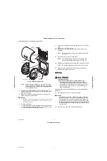
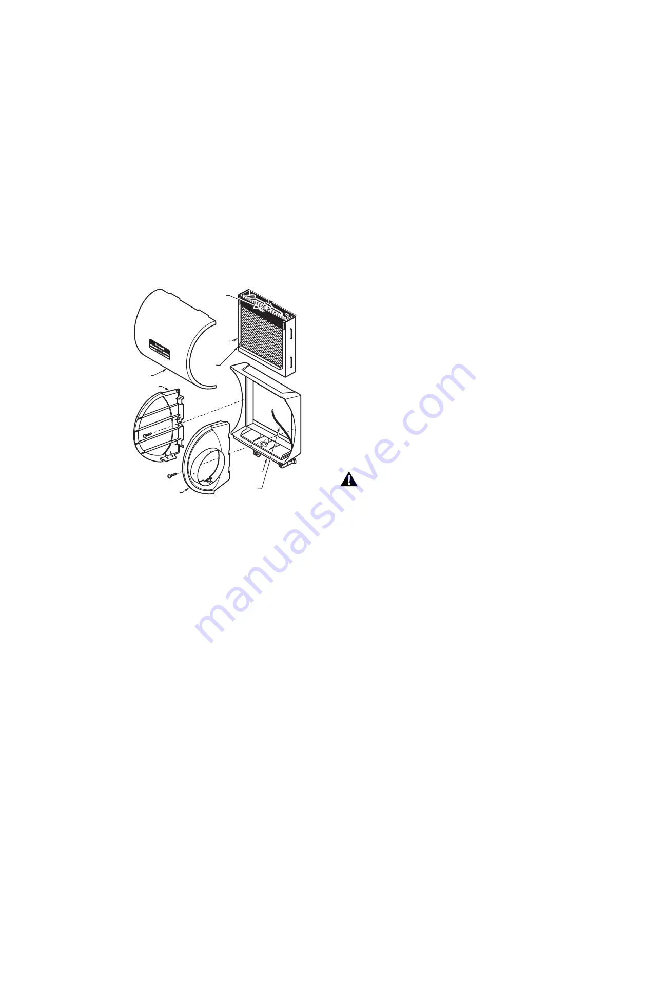
Fig. 2. Humidifier components.

NOTE: Sidewalls are interchangeable for either left or right 

bypass installation. To change direction, remove the 

screws holding each sidewall, switch sidewall locations 

and reinstall the screws.

5.

Position the humidifier housing in the opening (be sure it is 

level), so the locking tabs are in place on the lower sheet metal 

edge of the opening. 

6.

Secure the humidifier housing to the opening at the top and 

bottom using sheet metal screws.

IMPORTANT 

The damper is specifically designed with snap features for use spe-

cifically with Honeywell humidifiers. It is not intended for use in 
any other application.

7.

To install the damper:

a. Insert the damper into the humidifier with the selector knob 

aligned with the forward-facing hole in the humidifier collar.

b. Twist the damper until it snaps into place.

8.

Locate the other plenum and cut an opening for a 6 in. (152 mm) 

collar.

9.

Install the 6 in. (152 mm) collar.

10.

Install a 6 in. (152 mm) diameter duct from the collar to the 

humidifier.

NOTE: Some installations require a 90° elbow attachment to 

the collar.

11.

Seal the duct connections with duct tape. 

NOTE: To avoid sagging and stress on the humidifier, add

support when ducting is longer than 4 ft (120 cm).

12.

Reinstall the humidifier pad assembly in the humidifier housing.

NOTE: Be sure the water feed tube is not pinched or kinked. 

13.

Hinge the cover in place and secure with the thumbscrew 

located at the bottom of the cover.

WIRING

WARNING

Hazardous Voltage.

Can cause personal injury or equipment damage.

• Disconnect power supply before installing or servicing.

• On multispeed blower applications, do not wire the high 

voltage side of the transformer to the same power source 

that services the furnace blower or the transformer may 

burn out prematurely. 

All wiring must comply with applicable local codes, ordinances and 

regulations.

14.

Mount the transformer in a convenient location.

IMPORTANT

Install transformer on the outside of a grounded metal junc-

tion box using only a 7/8 in. (22 mm) knockout hole. Place 

mounting tabs into the knockout hole and firmly tighten the 

locking screw. Field wiring connections and grounding means 

for the transformer and enclosure shall be in accordance with 

the National Electrical Code (NEC) and the Canadian Electri-

cal Code (CEC).

15.

Connect wires to the 120V side of the transformer.

  M31022

WATER

FEED NOZZLE

FRAME

HUMIDIFIER

HOUSING

WATER

FEED TUBE

HUMIDIFIER

PADASSEMBLY

COVER

SIDEWALL

BY-PASS SIDEWALL

Summary of Contents for HE225

Page 1: ... supply plenum static pressure is no greater than 0 3 in w and water pressure is no greater than 125 psi IMPORTANT To assure optimal product performance be sure the template is level before marking 1 Determine the best location for the humidifier and draw a level line on the plenum See Fig 1 Fig 1 Typical humidifier installation locations IMPORTANT Mount the humidifier at least 3 in 76 mm above th...

Page 2: ...a 90 elbow attachment to the collar 11 Seal the duct connections with duct tape NOTE To avoid sagging and stress on the humidifier add support when ducting is longer than 4 ft 120 cm 12 Reinstall the humidifier pad assembly in the humidifier housing NOTE Be sure the water feed tube is not pinched or kinked 13 Hinge the cover in place and secure with the thumbscrew located at the bottom of the cove...

Page 3: ...er flow The valve is either open or closed To prevent debris from clogging the solenoid in line filter be sure to install the saddle valve handle pointing toward the ceiling NOTE Lightly clean the copper tubing ends with fine sand paper before making any connections 2 Use 1 4 in O D copper tubing and connect the saddle valve to the inlet side of the solenoid valve a Place the brass compression nut...

Page 4: ...ate entire sheet U S Registered Trademark 2010 Honeywell International Inc 69 1425EF 03 K K Rev 06 10 Printed in U S A Automation and Control Solutions Honeywell International Inc 1985 Douglas Drive North Golden Valley MN 55422 Honeywell Limited Honeywell Limitée 35 Dynamic Drive Toronto Ontario M1V 4Z9 customer honeywell com ...

Page 5: ...entation dans le plenum ne dépasse pas 0 3 po c e et que la pression de l eau ne dépasse pas 125 psi IMPORTANT Avant de marquer l emplacement vérifier si le gabarit est de niveau pour assurer le rendement optimal de l appareil 1 Déterminer l endroit le mieux approprié pour l humidificateur et tracer une ligne de niveau sur le plenum Voir la Fig 1 Fig 1 Emplacements types de l humidificateur IMPORT...

Page 6: ...oude de 90 doit être fixé au collet 11 Sceller les raccords de la gaine avec du ruban à gaine isolant REMARQUE Si la gaine mesure plus de 120 cm 4 pi de longueur installer des supports pour éviter son affaissement et les contraintes sur l humidificateur 12 Remettre l ensemble écran évaporateur dans le boîtier de l humidificateur REMARQUE S assurer que le tube d arrivée d eau n est ni écrasé ni tor...

Page 7: ...binet vanne doit être soit ouvert soit fermé S assurer que la poignée du robinet vanne à étrier pointe vers le plafond lors de l installation pour prévenir que des débris ne bloquent l électrovanne dans le filtre du tuyau REMARQUE Avant d effectuer les raccords nettoyer légèrement l extrémité des tuyaux avec un papier de verre fin 2 Utiliser un tuyau en cuivre de 1 2 de po de diamètre extérieur po...

Page 8: ...barit feuille entière Solutions de régulation et d automatisation Honeywell International Inc 1985 Douglas Drive North Golden Valley MN 55422 Honeywell Limited Honeywell Limitée 35 Dynamic Drive Toronto Ontario M1V 4Z9 customer honeywell com Marque de commerce déposée aux É U 2010 Honeywell International Inc Tous droits réservés 69 1425EF 03 K K Rev 06 10 Imprimé aux É U ...

Reviews: