Automation and Control Solutions
Honeywell International Inc.
Honeywell Limited-Honeywell Limitée
1985 Douglas Drive North
35 Dynamic Drive
Golden Valley, MN 55422
Toronto, Ontario M1V 4Z9
customer.honeywell.com
® U.S. Registered Trademark
© 2009 Honeywell International Inc.
69-1428—01 E.K. Rev. 06-09
Template (entire sheet) Top of Humidifier
Template (entire sheet)
Te
mplate (e
nt
ir
e sh
ee
t)
Te
mp
late (entire sh
eet)
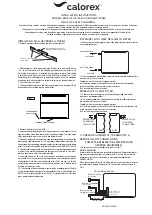
Fig. 5. Typical wiring diagram for humidifier using fan control to
cycle blower motor fan and humidifier simultaneously.
Fig. 6. Typical wiring diagram of current sensing relay with
humidifier.
Fig. 7. Typical wiring diagram of sail switch with humidifier.
For H1008 Automatic Humidity Control wiring
connections:
IMPORTANT
• Current sensing relay or sail switch is not needed with the
Automatic Humidity Control.
• Use 18-22 gauge insulated wire for proper wiring. We
recommend stranded - tinned wire.
Connect 24 Vac power to the 24 Vac HOT and COM terminals on
the H1008A.
14.
Connect the humidifier to the two HUM terminals on the
H1008A as shown in Fig. 8.
For additional mounting and wiring information, refer to the Humidity
Control installation instructions.
For Perfect Climate Comfort Center
™
Control
connections:
1.
Connect only the two yellow wires to the W8900 (red wire con-
nections are not used). See the typical wiring diagram in
Fig. 9.
For additional mounting and wiring information, refer to the Perfect
Climate Comfort Center
™
installation instructions.
Plumbing Saddle Valve
Hot or cold water, either hard or softened, can be used in the
humidifier.
1.
1.
Use the self-piercing saddle valve (included) to tap into the water
supply line at an appropriate location.
CAUTION
Chemical Hazard.
Can cause personal injury or equipment damage.
Do not use any line connected to an air conditioner.
IMPORTANT
• •The saddle valve is not designed to regulate water flow; the
valve is either open or closed.
• •To prevent debris from clogging the solenoid in-line filter, be
sure to install the saddle valve handle pointing toward the
ceiling.
NOTE: Lightly clean the copper tubing ends with fine sandpaper
before making any connections.
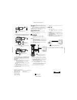
Fig. 8. Typical wiring diagram for humidifier using TrueIAQ.
2.
Use 1/4 in. O.D. copper tubing and connect the saddle valve to
the inlet side of the solenoid valve.
a. Place the brass compression nut over the copper tubing.
b. Slide the brass ferrule over the tubing.
NOTE: Do not over-tighten the compression nut. Moderate
tightness prevents leaking.
c. Insert the tubing into the solenoid valve fitting and support
the valve while tightening the compression nut.
NOTE: Slope hose downward for correct drainage.
3.
Connect a 1/2 in. hose to the humidifier drain fitting and run it to a
suitable drain.
CHECKOUT
1.
Open the saddle valve.
NOTE: The furnace blower must be on for the humidifier to
operate.
2.
Set the thermostat setpoint 10°F (6°C) above the room
temperature.
3.
Set the humidity control to a high humidity setting, or place the
setting in the test position.
4.
Observe the water running out of the drain line to be sure the
humidifier is working correctly.
5.
Check for leaks.
6.
Reset the thermostat to a comfortable setting or the Automatic
Humidity Control to the desired frost factor setting.
Fig. 9. Typical wiring diagram for humidifier using VisionPROIAQ
HUMIDIFIER
MECHANICAL
HUMIDISTAT
120 VAC
TO BLOWER
MOTOR
IGNITION BOX
M12686A
YELLOW WIRES
1
1
2
2
POWER SUPPLY. PROVIDE DISCONNECT MEANS AND
OVERLOAD PROTECTION AS REQUIRED.
24V WIRING.
CURRENT
SENSING
RELAY
HUMIDIFIER
120 VAC
BLOWER
MOTOR
C
LO
HI
M12684A
YELLOW WIRES
1
1
2
2
POWER SUPPLY.
PROVIDE DISCONNECT
MEANS AND OVERLOAD
PROTECTION AS REQUIRED.
24V WIRING.
MECHANICAL
HUMIDISTAT
SAIL
SWITCH
HUMIDIFIER
120 VAC
M12685A
YELLOW WIRES
1
1
2
2
POWER SUPPLY. PROVIDE DISCONNECT
MEANS AND OVERLOAD PROTECTION
AS REQUIRED.
24V WIRING.
MECHANICAL
HUMIDISTAT
HVAC
TrueIAQ
THERMOSTAT
HUM
HUM
R
C
W
G
G
Y
W
R
Rc
G
Y
W
R
C
YELLOW
required to isolate the G wire.
TH8320 or TH8321 is used, a relay may be
TH5320, TH6110, TH6220, TH6320, TH8110,
If a thermostat other than TH5110, TH5220,
1
1
M31027
Yellow
HUM
1 Set VisionPRO IAQ ISU #372 and #374 to
control for frost and HVAC fan operation.
M30128