4. Set Up and Calibration Procedures - Calibration
60
10260S HercuLine® Actuator Installation, Operation and Maintenance Manual
Revision 5
7/07
Calibrate Input
The 10260S actuator accepts a variety of signal inputs.
1.
0 mA to 20 mA, or 4 mA to 20 mA
2.
0 Volts to 5 Volts, 1 Volt to 5 Volts, or 0 Volts to 10 Volts
The input type is selected through the Input set up group using the local keypad.
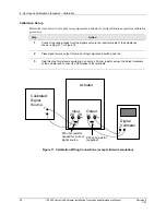
Refer to Figure 17 for the wiring connections and follow the procedure in Table 23 to calibrate the input
circuit of the 10260 S actuator.
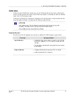
ATTENTION
For an input calibration to be saved, you must complete the procedure. The calibration will not
be saved if you exit without completing the steps of the procedure.
To exit calibation mode, press DISPLAY or SETUP keys.
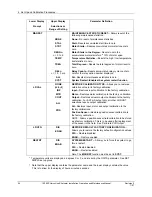
Table 23 Input Calibration Procedure
Step
Operation
Press
Result
1
Enter Calibration
Mode
SETUP
until you see
Upper Display
=
CAL
Lower Display
=
INPUT
FUNCTION
Upper Display
=
DIS
Lower Display
=
CAL IN
or
key
Upper Display
=
BEGN
Lower Display
=
CAL IN
2
Calibrate Zero (0%)
FUNCTION
Upper Display
=
APLY
Lower Display
=
INZERO
•
Adjust the signal source to an output value equal
to 0% range value.
•
Wait 5 seconds, then go to step 3.
3
Calibrate Span
(100%)
FUNCTION
Upper Display
=
APLY
Lower Display
=
INSPAN
•
Adjust the signal source to an output value equal
to 100% range value.
•
Wait 5 seconds, then go to step 4.
4
FUNCTION
Calibration for zero and span input values are now
saved. Input calibration is complete.
NOTE: . You may also exit calibration mode by
pressing the DISPLAY or SETUP keys.
Summary of Contents for HercuLine 10260S
Page 10: ......
Page 94: ......
Page 121: ......
Page 122: ...Honeywell Field Solutions Honeywell Inc 512 Virginia Drive Fort Washington PA 19034 ...


