background image


Honeywell


VENTI


Series 

HICC-0100P/HICC-0100N Box Camera 

User Guide 


Summary of Contents for HICC-0100N

Page 1: ...Honeywell VENTI Series HICC 0100P HICC 0100N Box Camera User Guide ...

Page 2: ...Revisions Issue Date Revisions A 11 03 New document for HICC 0100 release Generally describes the functionality in the firmware of the HICC 0100 camera ...

Page 3: ...re Requirements 6 Connecting the Camera to a Personal Computer 7 Setting IP 7 Connecting the Camera to a Personal Computer 7 Using IP Finder to Search Camera s IP Address 9 4 Overview of Navigation and Controls 10 Live View 10 Image Parameters 10 Basic 11 Compression 13 Alarm 17 OSD 19 FTP Recording 19 SD Recording 21 E mail Recording 24 Audio 26 Network Settings 27 Basic 27 Admin Function 31 Admi...

Page 4: ...Honeywell ii ...

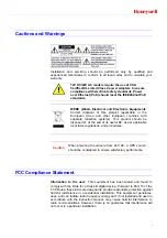
Page 5: ...posed of at the end of its useful life as per applicable local laws regulations and procedures Caution When powering the camera from 24V AC a UPS source should be considered to ensure satisfactory performance FCC Compliance Statement Information to the user This equipment has been tested and found to comply with the limits for a Class B digital device Pursuant to Part 15 of the FCC Rules these lim...

Page 6: ... compliant with the essential protection requirements of EMC directive 2004 108 EC and General Product Safety Directive GPSD 2001 95 EC conforming to requirements of standards EN 55022 for emissions EN 50130 4 for immunity Warranty and Service Subject to the terms and conditions listed on the Product warranty during the warranty period Honeywell will repair or replace at its sole option free of ch...

Page 7: ...w introduces the main functions and system requirements of the camera Chapter 3 Installation and Connections provides detailed instructions on installing the camera and connecting wires Chapter 4 Overview of Navigation and Controls introduces how to navigate in the main menu window and operate the controls Appendix A Troubleshooting lists common problems encountered when setting up the network cam...

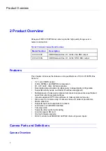
Page 8: ...esolution Dual digital video streams simultaneously independently configurable Supports both Dynamic and Static IP address assignment Multiple levels of password protected remote access prevents unauthorized users from altering system settings Includes advanced IP Finder software to make system setup easy Web server for remote setup of camera video and network parameters Motion detection Supports ...

Page 9: ... Definitions 1 CS mount connect the lens with the camera 2 Screw 3 Back focus Adjustment 4 Base connect the camera with the tripod 5 SD card slot insert a SD card into this slot for recording and storage 6 Video video output port ...

Page 10: ...et all of the camera parameters to factory default 9 Reset Button restart the system 10 Power Indicator Red light indicates power connection 11 I O Connector Input Output Connector 12 Power Terminal DC12V AC24V red port power white port power black port GND Make sure to connect the power connector to correct ports and when the power supply is DC12V ...

Page 11: ... Unpack Everything One HICC 0100P N Camera 3 pin terminal block for power input and 4 pin terminal block for alarm input output Quick Installation guide One CD containing the software Equipment Required The following tools might help you to complete the installation Drill Screwdrivers Wire cutters Camera Installation Note All the installation and operations here should conform to your local electr...

Page 12: ...ith the list on the warranty card Finally you can remove the protective film of the camera Mounting 1 Attach the camera to a pending mount Insert the screws on the camera stand into either of the screw holes on the base Then tighten them up 2 Mount the camera onto the ceiling wall and fasten it securely Network Camera Diagram Connection type1 Connection type 2 Hardware and Software Requirements Co...

Page 13: ...in an IP address automatically from the DHCP server You don t need to change the camera s IP address if your network uses a DHCP server Connecting the Camera to a Personal Computer 1 Connect the network cable to the camera and then turn on the camera s power 2 Set the personal computer s IP address The camera s default IP address is 192 168 0 30 and sub mask is 255 255 255 0 3 Check that the camer...

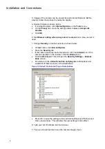
Page 14: ...menu click Internet Option Press the Security tab If the camera operates inside the intranet click the Intranet icon If the camera operates on the Internet click the Internet icon Click Custom Level This will open the Security Settings Internet Zone screen Scroll down to the ActiveX controls and plug ins radio buttons and enable all of them as shown in the illustrations Figure 3 2 ActiveX Controls...

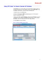
Page 15: ...a and Windows XP 1 Insert the CD in the CD ROM drive 2 Double click Honeywell_VENTI_IP_Camera vx exe to run the program Follow the instructions to install 3 After successfully installing IP Finder double click the IP Finder icon which is displayed in your desktop An IP Finder window will pop out The window will display a list of net cameras which you are using currently 4 Press Search to search ca...

Page 16: ...een Set Full screen Deinterlace One shot take a picture from live view Manual Record Primary Stream Secondary Stream Two streams are available for selection among H 264 MPEG 4 and MJPEG Figure 4 1 Live View Image Parameters You can setup Basic Setting Image Compression Alarm OSD FTP E mail SD Recording and Audio for your network IP camera by clicking on network setting on setting menu ...

Page 17: ... Exposure Automatic Exposure controls the light intensity of picture There are two types for adjustment You can select manual or AES Automatic Electronic Shutter for the camera depending on your application conditions When choose the Manual the Shutter speed can be adjusted Shutter Speed ...

Page 18: ...rnal lighting condition OFF Adjustable by user manually this is useful for some specific conditions which AWB may be unaffordable to perform correctly You can set the current R G B color temperature manually R Gain B Gain Figure 4 6 R Gain B Gain Set manual gain value of R Gain B Gain from 1 to 255 This function is applied for manual lens only The red R gain is used to adjust the red color of the ...

Page 19: ...imum image level Due to the intense light coming from the back of objects in the area expected to view the auto iris lens tends to close and areas desired to see become dark and invisible Therefore this function is essential Picture Picture Flip Set image to be upside or down Select ON or OFF to activate or deactivate the flip function Picture Mirror Set image to be left or right Select ON or OFF ...

Page 20: ...cture Quality Besides the network camera supports dual streams for display and storage should be configured separately 1 The user interface of Primary Stream is as follows Figure 4 10 Primary Stream Table below elaborates the above one Table 4 1Compression Compression Item Function Choice Remark Primary Stream Image Mode MJPEG Set a default compression mode MPEG4 H 264 Resolution D1 D1 is the high...

Page 21: ...s setting produces lowest image quality while the file size decreases Quality value MJPEG 3 90 MPEG4 H264 1 31 selectable Bit Rate 256K 512K 1M 2M 3M 4M It s optional only when constant bit rate is chosen Select the desired bit rate including 256 512 1M 2M 3M and 4M kb s GOP 1 64 Select the GOP Group of pictures number from 1 to 64 If the number is bigger recovery of the lost frames will be more d...

Page 22: ...de MPEG4 H264 no streaming Resolution D1 4CIF 2CIF CIF D1 is the higher resolution and QVGA is the lower resolution VGA QVGA Frame Rate 1 30 The frame rate that is displayed per second PAL H 264 MJPEG D1 4CIF 2CIF CIF VGA QVGA 25fps MPEG4 VGA QVGA CIF 25fps NTSC H 264 MJPEG D1 4CIF 2CIF CIF VGA QVGA 30fps MPEG4 VGA QVGA CIF 30fps Rate control mode variable bit rate Choose the Bit Rate control sele...

Page 23: ...aller it will increase the bite rate obviously and aggravate the network load The default value is 30 Profile Baseline selectable Main Profile High Profile Note Please click the Save button to save your image settings You can also click the left button Reset to Default to set all the data and options as defaults Alarm External Digital Input 1 When alarm input is connected the camera triggers an al...

Page 24: ...e to use this function or not by selecting ON or OFF Sensitivity Users can choose different levels of sensitivity which are High Mid and Low Figure 4 14 Sensitivity Text Enable Choose ON or OFF Text After you choose ON in item Text Enable you can type the name of your images Alarm Output Alarm Mode Set the Alarm Mode as Event When an alarm event is detected an alarm message appears on the Web Clie...

Page 25: ...l Position from 1 20 Note Please click the Save button to save your image settings You can also click the left button Reset to Default to set all the data and options as defaults FTP Recording You can save image files via FTP Set your FTP recording condition first and then identity your FTP server 1 and 2 To use FTP Recording make sure you have selected MJPEG as primary stream or secondary stream ...

Page 26: ...ed with Login ID Password Confirm Re enter the password FTP Port Number set 21 as default FTP Mode PORT mode This mode is for most FTP applications PASV mode This mode is for the camera s network environment is behind a firewall FTP Connecting Method Reconnect The network camera logs in out for each file transfer Continuous Connection The network camera is always in connection FTP Server usage Pri...

Page 27: ...ur image settings You can also click the left button Reset to Default to set all the data and options as defaults SD Recording This function is designed for storing images on the SD card Figure 4 20 SD Recording Users can choose recording conditions between Schedule Event and Network ...

Page 28: ...ections will come into being Figure 4 21 Conditions Scheduled Recording Select Schedule This function is designed for setting recording schedules Specify your recording settings by All Day or Schedule 1 or Schedule 2 Figure 4 22 Conditions2 Figure 4 23 Scheduled Recording Alarm Recording ...

Page 29: ...nction is only enabled after setting alarm input as alarm input See the picture below Figure 4 25 Alarm Settings Motion Recording Figure 4 26 Motion Recording When you choose Motion the camera will record by Motion and you can choose different recording time including 5s and 10s But this function is only enabled after setting motion detection as ON See the picture below ...

Page 30: ...ft button Reset to Default to set all the data and options as defaults E mail Recording You can receive images by setting your E mail account Conditions Figure 4 29 Email Recording Conditions You can choose the form of the E mail Recording of Alarm and Motion If choosing Motion should set Motion Detection as on in Alarm setting See the picture below Figure 4 30 Choosing Motion Detection Email Serv...

Page 31: ...ed across the network 4 LOGIN The LOGIN mechanism is supported by Microsoft s Outlook Express as well as by some other clients 5 TLS START TLS when select this item you can change the data beside it Figure 4 32 Choosing TLS START TLS E mail Server SMTP Enter your outgoing mail server SMTP E mail User ID Input your E mail account ID number Password Input your E mail account password Password Confir...

Page 32: ...on occurs Note Please click the Save button to save your image settings You can also click the left button Reset to Default to set all the data and options as defaults Audio You can set up your audio setting by enabling audio input and output Figure 4 35 Audio Settings Format Figure 4 36 Format Format Support two audio compression formats of A law and U law Audio Input Audio Input Set to ON when r...

Page 33: ...r use the default name Network DHCP The IP address is automatically obtained when you select ON otherwise select OFF to manually setup the network setting IP Address Input your IP address here when you select DHCP off Subnet Mask Please use default number 255 255 255 0 If the subnet mask is not properly configured the camera may not be able to communicate with other devices on the network Default ...

Page 34: ...nnecessary to install the IP Finder program Bonjour Use When set to ON the camera can be detected automatically by the device which support Bonjour protocol It is unnecessary to install the IP Finder program Figure 4 39 Bonjour Use Note Please click the Save button to save your image settings You can also click the left button Reset to Default to set all the data and options as defaults DDNS In th...

Page 35: ...l the data and options as defaults FTP Server In this page you can activate a FTP server if you want to Tick ON to activate the FTP function Then you should follow the following procedures to set up related settings Or OFF to disable the FTP function and you can skip the following procedures Enter a login ID if you activate the FTP function Enter a password associated with a login ID Re enter the ...

Page 36: ...P Authentication You should enter the Login ID Password and Password confirm if select ON Figure 4 43 Authentication Multicast Address You could choose the value from 224 0 0 23 to 239 255 255 254 Figure 4 44 Multicast Address Primary Stream Secondary Stream Figure 4 45 Primary Stream Secondary Stream Please choose desired options and value and remember to click save button to save all your settin...

Page 37: ...eld Figure 4 47 Administrator Settings Note Please click the Save button to save your image settings You can also click the left button Reset to Default to set all the data and options as defaults User List Besides administrator guests can access the camera under authorization from system administrator by ID and password controller However User1 5 are allowed to review the live picture only Withou...

Page 38: ...en the user can go on to choose Synchronization Mode Set Date and Time Manually Set up the camera s date and time in the Set Date and Time Manually field Figure 4 51 Set Date and Time Manually Set Date and Time By NTP Server 1 Time Zone Select the time zone where your camera is located 2 NTP Server Select NTP in the Synchronization Mode If NTP is selected the date and time will be synchronized by ...

Page 39: ... as defaults Update You can update system firmware if the update file is available It is the customer s responsibility to update firmware All camera motions will shut down during firmware update Close any other screens before starting a firmware update Never disconnect power and LAN cable during the firmware update process Rebooting the camera after firmware update may take approx 15 minutes After...

Page 40: ...ings This function is designed to export configuration settings to the client computer Figure 4 56 Export Configuration Settings Set to Factory Default This function is designed to reset all configuration settings into factory default Figure 4 57 Set to Factory Default Network Camera Reboot This function is designed to reboot the camera Figure 4 58 Network Camera Reboot Event Log Click the buttons...

Page 41: ...Honeywell 35 Figure 4 59 Log Browse Information FW version and MAC address will be shown Figure 4 60 FW version and MAC address ...

Page 42: ...st be clearly marked on all return packages and internal paperwork Problem Lens out of Optical Focus Possible solutions 1 Verify that the lens cap has been removed from the camera 2 This can also be cause by dirt oil grease and fingerprints and so on that have accumulated on the lens or bubble Check the lens and bubble and then clean them if needed Caution Use extreme caution when cleaning the len...

Page 43: ...OS Sensor Effective Pixel 680H 512V Service monitor Output For installation Yes Lens mount CS mount Analog out PAL NTSC Electric Lens N A Mechanical D N N A Sync system Internal S N ratio 50dB Gamma correction 0 45 1 Auto gain control On White balance ATW Manual Electric shutter 1 50 1 10000 sec PAL 1 60 1 10000 sec PAL BLC Off On Audio Two way Mono Audio Alarm 1 in 1 out SD card Yes Video output ...

Page 44: ...ge temperature 20 C 60 C Waterproof N A Network Ethernet 1 10 100 base T Ethernet connection for LAN WAN Security Multiple user access levels with password protection Users 1 Administrators 5 Guests Multiple Client Access 3 clients simultaneously real time Video Access from Web Browser Full control of all camera settings available to administrator Min web browsing requirements Pentium IV CPU X2 2 ...

Page 45: ...seT 100BaseTX PoE Video port BNC Connectors RJ 45 10BaseT 100Base TX Power connector Spring terminal type Terminal blocks for audio in audio out Terminal blocks for 1 alarm in 1 alarm out 1 reset button 1 default button Mechanism Dimensions L W H 56mm H 68mm W 125mm L Weight 650g Regulatory Specifications Emissions FCC CE EN55022 Immunity CE EN50130 4 ...

Page 46: ...Glossary 40 7 Glossary ...

Page 47: ...ell Honeywell Security Asia Pacific 35F Tower A City Center 100 Zun Yi Road Shanghai 200051 China TEL 86 21 22196888 FAX 86 21 62370740 http www security honeywell com 2011 Honeywell International Inc All rights reserved ...

Reviews: