background image

HONEYWELL SECURITY TECHNICAL BULLETIN


11 December 2008


www.asia.security.honeywell.com                                                                                               Rev 1.0                        

1 of 5 


Honeywell Video Systems 

Subject: Control HNDR-S 4848 DVR by VideoBlox HEGS5BLX


Introduction 

 
This document describes the Protocol Interface Translator (PIT) operation specific to the Honeywell HNDR-S 
series DVR. For further details on the PIT, please refer to the PIT User manual. For further details on the DVR, 
please refer to the appropriate Honeywell HNDR-S DVR manual. 
 
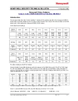
Quick Start Switch Settings 
 

Output 

Protocol 

S1/8 S1/7 S1/6 S1/5 S1/4 S1/3 S1/2 S1/1 


Valid 

Function 

Valid 

Function 

Valid 

Function

Valid 

Function

ASCII 

string 

mode 

ASCII 

string 

mode 

ASCII 

string 

mode 

ASCII 

string 

mode 

  Off Off Off Off On On On On 


Address 

S2/8 S2/7 S2/6 S2/5 S2/4 S2/3 S2/2 S2/1 

Switch 

Legend 

Address 

Address 

Address 

Address 

Address 

Address 

Address 

Address 

0 (B/cast) 

Off 

Off 

Off Off Off Off Off Off 


Input 

Protocol 

S3/8 S3/7 S3/6 S3/5 S3/4 S3/3 S3/2 S3/1 


Slave Port 

Baud 

Slave 

Port 

Baud 

Master 

Port Baud

Master 

Port Baud

Input 
Type 

Input 
Type 

Input 
Type 

Input 
Type 

Bossware 

On  Off On Off On On On Off 

 
The above setting set the PIT as follows: 
 
Receive Betatech compatible Bossware control messages on the RS422 slave port of the PIT at 19.2K baud. 
The PIT unit address (S2/1 - S2/8 to OFF position) is set to broadcast, so all addresses will be translated. If 
want to control specific unit of DVR, set the dip switch S2/1 – S2/8 of PIT address and add PIT per DVR. (It is 
tested the address from 1 to 128.) 
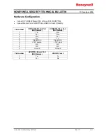
 

Unit 

ID 

S2/8 S2/7 S2/6 S2/5 S2/4 S2/3 S2/2 S2/1 

1  Off Off Off Off Off Off Off On 
2 Off


Off


Off


Off


Off


Off On Off 

3 Off


Off


Off


Off


Off


Off On On 

4 Off


Off


Off


Off


Off


On Off Off 

5 Off


Off


Off


Off


Off


On Off On 


255 On On On On On On On On 

Transmit Honeywell HNDR-S control messages on the RS422 master port at 9600 baud, 8, N, 1 . 

 
Note: To control HNDR-S series DVR, the DVR firmware should be 1.0.17 or later. 
 
(Tested firmware: HVBCPUX – 4.96x 

HVBCFG – 3.08 (Build 32) 

HVBPIT44 – 3.03) 

Summary of Contents for HNDR-S 4848

Page 1: ...ff Off Off Off Off Input Protocol S3 8 S3 7 S3 6 S3 5 S3 4 S3 3 S3 2 S3 1 Slave Port Baud Slave Port Baud Master Port Baud Master Port Baud Input Type Input Type Input Type Input Type Bossware On Off On Off On On On Off The above setting set the PIT as follows Receive Betatech compatible Bossware control messages on the RS422 slave port of the PIT at 19 2K baud The PIT unit address S2 1 S2 8 to OF...

Page 2: ...ter Port to Slave Port of HVBPIT44 Connect Master Port of HVBPIT44 to HNDR S Com 2 RS 485 Pin Number CPU RS422 Master Port DB9 Female HVBPIT44 Slave Port DB9 Female 1 Tx Rx 2 Tx Rx 3 Rx Tx 4 Rx Tx 5 Signal Gnd Signal Gnd 6 12V source 12V input 7 NC NC 8 NC NC 9 Ground Ground Pin Number HVBPIT44 Master Port DB9 Female HRHD S Com 2 1 Tx Tx 2 Tx Rx ...

Page 3: ...to browse HNDR S db which is locate in C Program Files Honeywell VBloXCFG DBF 5 Set Com Port to 1 if the control signal to the device is connected to the VideoBloX CPU master communications port 6 Set the Control Type to the type of interface used to control the external device 7 Set Switch Offset to 1 if no automatic video switch operation is required when the device is selected The offset will b...

Page 4: ...Push Menu button of DVR and enter the DVR setting menu b Move to System menu and select Serial Setup c Move to COM2 485 and select Keyboard HTX 3000 as below figure 2 Configure Keyboard Control Address and Keyboard PTZ address as below figure a Push Menu button of DVR and enter the DVR setting menu b Move to Miscellaneous menu c Select Keyboard Control Address to 1 ...

Page 5: ...ss C 5 Search Press C 6 Sequence Press F 7 Select AUX Mode LED on Press E 8 Multi screen AUX Mode LED on Press F 9 Exit AUX Mode LED on Press G 10 Enter AUX Mode LED on Press H 11 Up Hold down ALT Up 12 Down Hold down ALT Down 13 Left Hold down ALT Left 14 Right Hold down ALT Right I Use to move between menu items J Select DVR channel depending on the position K Select DVR channel depending on the...

Reviews: