Basics
for installing the device in a pipe
HON 5020 gas pressure regulator with HON 630 pilot
31
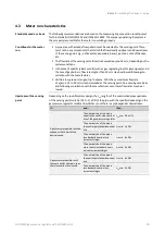
Depending on the specific system design, the L
uR
lengths of the undisturbed pipes down-
stream of the sensing point must be (1.5
to
4)
x
DN of the pipe:
Undisturbed length of pipe
for
L
uR
min.
1.5
x
DN
Thermowells
L
uR
min.
1.5
x
DN
Reducers and expanders, depending on the
specific system conditions
L
uR
min.
3
x
DN
Shut-off devices (gate valves, check valves, and
reduced bore ball valves)
L
uR
min.
4
x
DN
Tees
Shut-off devices with an undisturbed flow pattern (such as full bore ball valves) and, if
applicable, pipe bends (depending on the design) are considered to be non-disturbing
elements in terms of measuring line connections.
For gas meters (turbine gas meters including quantometers, ultrasonic gas meters, and
vortex flow meters, but NOT rotary piston gas meters), there are no restrictions in terms
of measuring line configurations, as these meters are not considered to be
flow-disturbing within this context.
The following applies to rotary piston gas meters: Minimum distance between gas
pressure regulator or reducer / expander and gas meter:
L
uR
min.
3
x
DN
.
Measuring line connections downstream of gas meters must be at a distance of
L
uR
min.
2
x
DN
.
If shut-off valves are used (reduced bore), the recommended distance downstream of a
measuring line is
L
uR
min. 3 x DN
.
Gas meter pressure losses must be taken into account based on system conditions if
applicable.
4.4
Operating and measuring lines
The lines must be arranged and sized in such a way that the devices’
intended function will be
ensured.
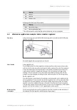
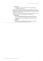
Measuring line
The measuring line transmits the pressure process value from the sensing
point to the measuring diaphragm of a controller or the pilot of a gas pressure
regulator or safety relief valve or to the measuring diaphragm of the moni-
toring device of a slam-shut device. It needs to be connected to the pipe
sideways or upwards separately for each device. In the case of safety equip-
ment, the measuring line must be connected upstream of the first outlet-side
shut-off device in such a way that it cannot be shut off. If the measuring line is
additionally connected downstream of the first outlet-side shut-off device,
3-way ball valves with negative overlap must be used for switching. These ball
valves do not have a valve position in which both measuring lines can be fully
closed at the same time.
Vent line
The vent line is used to connect a measuring diaphragm to the atmosphere. If
the measuring unit becomes damaged (e.g.,
diaphragm rupture), it can start
conveying gas. Under certain operating conditions, and following consultation
with the manufacturer, vent lines can be omitted if vent valves (HON
915) or
safety diaphragm configurations can be used instead.
Downstream of the
sensing point
Details
Connection lines between
device and gas regulating
line


