Maintenance
HON 512 with HON 650 pilot user manual
93
8.3.3
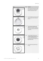
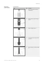
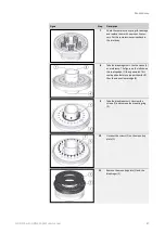
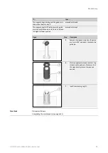
Maintaining the actuator assembly - Design 3
Crush and impact hazard posed by components falling or toppling over
accidentally.
When working with heavy components that have been removed or are yet to be installed,
injury may result if the components start moving in an uncontrolled manner, e.g., fall
down
from the working surface or topple over.
Place removed components exclusively on level, horizontal working surfaces with enough
load-bearing capacity.
If necessary, secure removed components so that they will not fall or topple over.
Wear the required personal protective equipment.
Exercise caution when performing the relevant tasks.
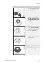
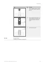
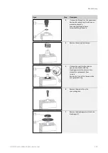
The maintenance described below is meant for devices with design
3 and nominal inlet sizes
of DN 25
–
DN 250, and uses the DN 50 Class
150 model as a reference.
Device models
(see
page 10)
Refer to the spare parts lists in the
appendix
(see page 152) to make sure that you replace all
the maintenance parts relevant to your device model during maintenance.
The tightening torques specified in the table apply to the maintenance instructions for the
actuator assembly. When screwing the body sections in step 25, the tightening torques must
be increased gradually. Start by tightening the screws with a third of the tightening torque,
then with two thirds, and, finally, with the full tightening torque in a criss-cross sequence.
Section
Tightening torque by DN nominal sizes in Nm (ft lbs)
Step
25
50
80
100
150
200
250
Maintaining
the actuator
assembly
25
-
-
-
-
425 (315) 730 (540) 400 (295)
Observe the following cleaning instructions:
▪
Before assembly, all parts must be cleaned in order to remove any foreign particles
(swarf) and soiling.
▪
Aside from one exception, the oil on screws and washers must be removed in advance
when they are being used as new parts to replace identical parts.
The exception are the screws that have a tightening torque specification as per the ta-
ble in the
Actuator assembly tightening torques
section. These screws must be screwed
in while still oiled.
Falling components
Sample maintenance
instructions
Actuator assembly tight-
ening torques
Cleaning
Summary of Contents for HON 512
Page 185: ...Appendix HON 512 with HON 650 pilot user manual 185 X Fail to open version Y Amplifying valve ...
Page 205: ...Appendix HON 512 with HON 650 pilot user manual 205 ...
Page 206: ...Appendix HON 512 with HON 650 pilot user manual 206 ...
Page 207: ...Appendix HON 512 with HON 650 pilot user manual 207 ...


