Maintenance
HON 670 / HON 671 Controllers Component Documentation
32
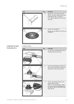
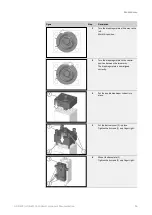
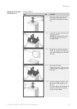
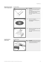
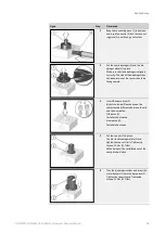
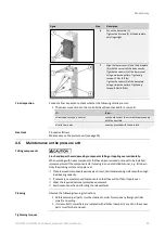
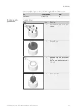
Proceed as follows:
Figure
Step
Description
1
Replace the O-ring (1) with a new, lubri-
cated O-ring.
Check the edge of the nozzle for damage.
Replace the nozzle if necessary.
Note: See the appendix for the lubricants
to be used.
2
Replace the diaphragm (1).
Place a new snap-on gasket (2) into the
new diaphragm.
3
Replace the O-ring (1) of the cap nut with a
new, lubricated O-ring.
Note: See the appendix for the lubricants
to be used.
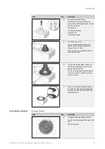
Proceed as follows:
Figure
Step
Description
1
Turn the nozzle (1) such that the pin (3) is
positioned coaxially to the bore.
Replacing the wear parts
of the diaphragm system
Assembling the dia-
phragm system

