Description
HON 670 / HON 671 Controllers Component Documentation
9
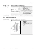
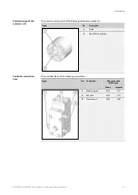
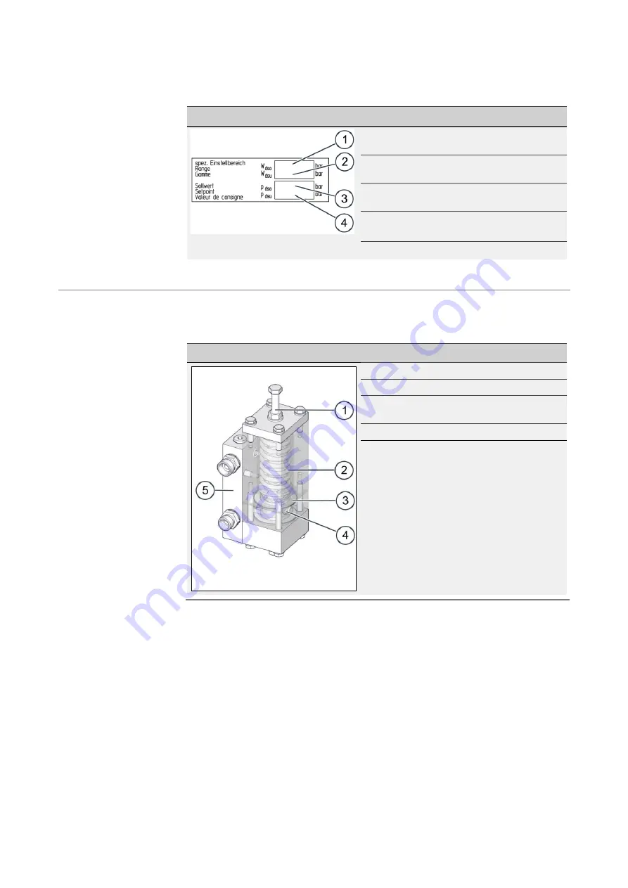
The details on the additional type plate mean the following:
Figure
No.
Description
1
Specific adjustment range [bar]
W
dso
= Excess pressure
2
Specific adjustment range [bar]
W
dso
= Insufficient pressure
3
Setpoint to be set [bar]
p
dso
= Upper response pressure value
4
Setpoint to be set [bar]; see configuration
p
dsu
= Lower response pressure value
Small color-
coded text labels must be used to mark the controller’s connection lines based on
what the lines are used for.
2.4
Physical design and operation
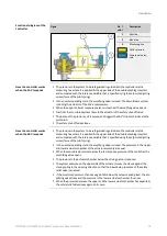
The controller is made up of the following individual components:
Figure
No.
Description
1
Spring adjuster
2
Pilot spring
3
Comparator stage with diaphragm meas-
uring unit
4
Amplifying valve
5
Base plate
Interpreting the addi-
tional type plate on the
monitoring device
Labels on connection
lines
Physical design of the
controllers K16 / K17


