CLSS Gateway - Installation and Users’ Manual | P/N:LS10248-000HW-E | REV. F | FEB/11/2022
113
ESSER Panels
Connecting to the Panels
•
IQ8 Panels
To Use an RS-485 Connection
Using an RS-485 cable, you can connect to the additional RS-485 module (784871) on
the panel's serial interface port.
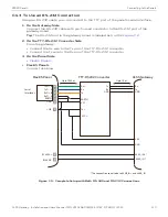
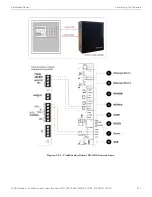
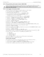
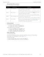
The RS-485 ports in the gateway board are labeled as 3 and 4 in the
On the Panel Side
Using an SEI2 Card
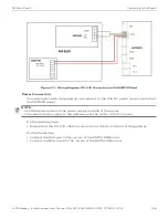
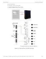
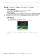
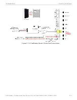
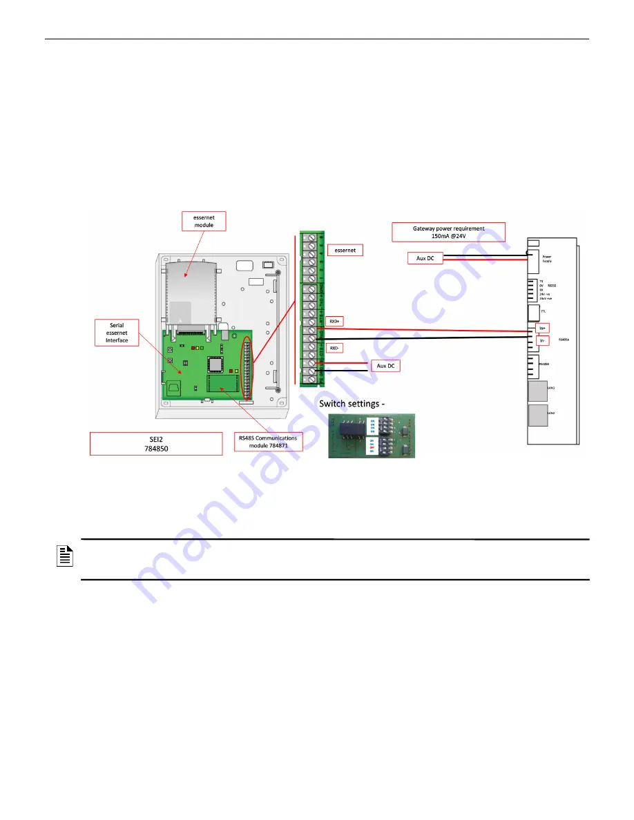
Connect to the RS-485 (784871) module in the panel as below:
In the RXD port of the panel’s SEI-2 card:
• Connect the In+ wire to the RXD+ pin.
• Connect the In- wire to the RXD- pin.
Figure C.7: Wiring Diagram: RS-485 to SEI2 Connection
Power Connection
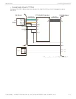
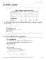
Using a power cable, the gateway can connect to the 12V DC power supply module of
the panel.
On the Gateway Side
• Connect the +ve wire to the +ve pin of the power supply port.
• Connect the -ve wire to the -ve pin of the power supply port.
On the Panel Side
• Connect the +ve wire to the +UBext pin of the SEI-2 card.
• Connect the -ve wire to the GND pin of the SEI-2 card.
NOTE:
Although the gateway is capable of receiving 24V DC power, it can work with the
12V DC power of the IQ8 panel. Ensure that the power supply to the gateway is within
+12V DC power.


