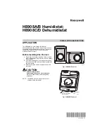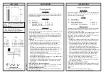

BAND
HUMIDISTATS
TYPICAL
PNEUMATIC
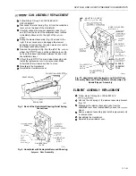
/ A S S E M B L Y
Follow steps through 4 of
Unhook the coil spring of the element assembly from
the
assembly bracket (Fig. IO).
Unhook the bias spring from its anchor post.
Remove the frame post and mounting screw.
Lift the nozzle/flapper assembly from the base.
Remove the O-ring from the rear of the nozzle/flapper
assembly.
Disengage the other end of the bias spring from the
bracket hole. Do not lose the small pin located inside
the spring.
Assemble the O-ring and the bias spring to the
replacement nozzle/flapper assembly and reinstall in
reverse order.
Recalibrate the
FILTER CARTRIDGE
Reinstall the tiumidistat cover.
AND
M
O
U
N
T
I
N
G
SCREWS (4)
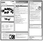
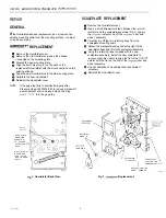
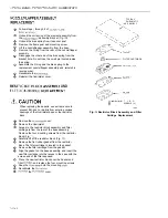
When replacing these parts, use extreme care to
prevent dirt, dust, or debris from entering various
openings of the Humidistat base or the restrictor
block.
Remove the
cover.
Remove the Humidistat.
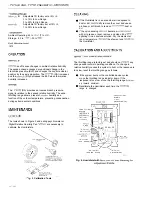
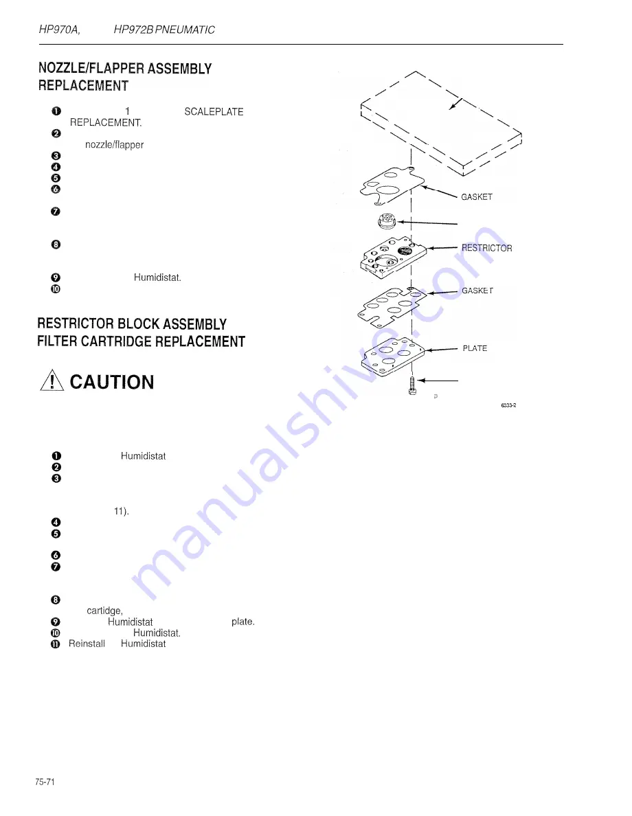
Fig. Il. Restrictor Block Assembly and Filter
Cartidge Replacement.
Access to the restrictor block assembly and filter
cartridge is from the rear of the base assembly.
Remove the four mounting screws from the restrictor
block (Fig.
Carefully lift off the restrictor block (Fig. 11).
Remove the flat rubber gasket from the restrictor
block. The filter cartridge is located in the gasket.
Remove the filter cartridge from the gasket.
Align the gasket on the base assembly, and insert the
new filter cartridge into the recess in the base with the
screen end of the filter exposed.
Place the new restrictor block over the hasket and
filter
and replace the four mounting screws.
Snap the
onto the mounting
Recalibrate the
the
cover.
9.5