HPF902ULADA Distributed Power Module Installation Manual
4-9
4.4
Connecting the HPF902ULADA to a FACP
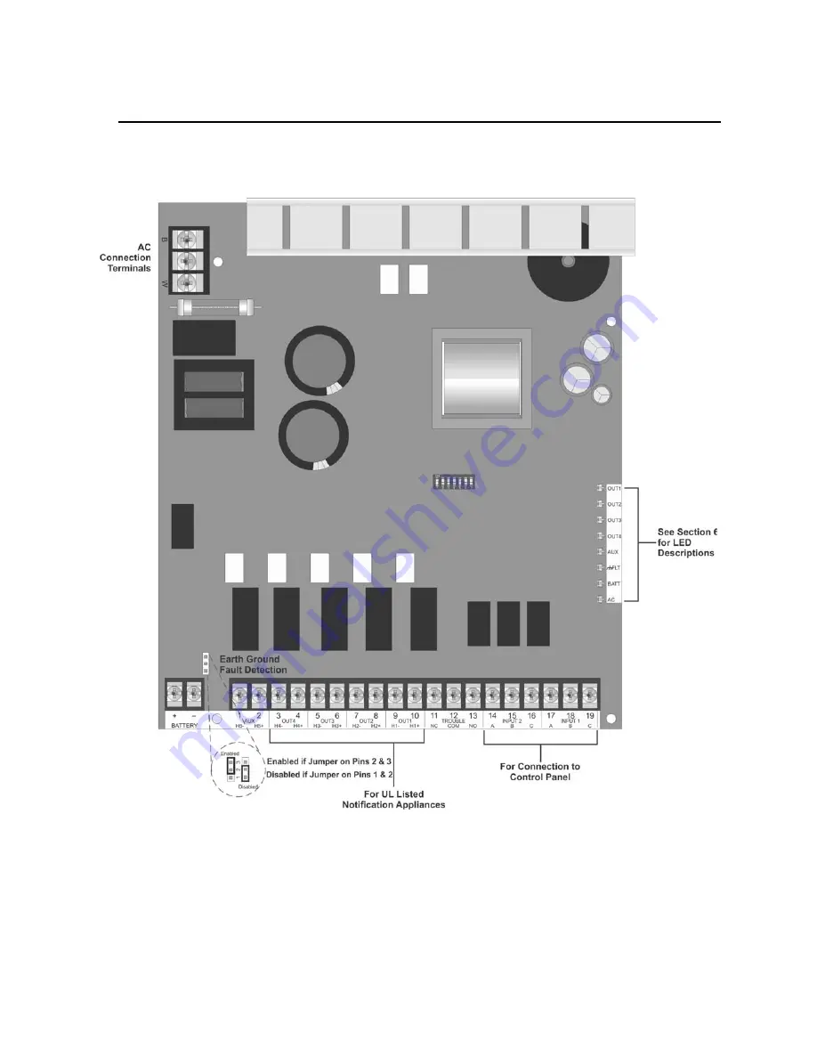
Figure 4-2 shows the general layout of the HPF902ULADA PC board. This section also provides specific wiring
details for accessories.
Figure 4-2 The Model HPF902ULADA PC Board Layout
Consult the installation manual for specific wiring information for the control panel being used.
4.4.1
Common Trouble Relay
The HPF902ULADA has a Form C trouble relay built into Terminals 11-13. The relay provides a normally open
and a normally closed contact, both of which are rated at 2.5A. The trouble relay will deactivate under any
trouble condition.
Summary of Contents for HPF902ULADA
Page 39: ......


