HPF902ULADA Distributed Power Module Installation Manual
4-17
4.8.2.5
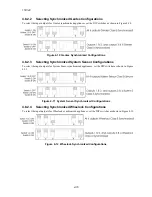
Selecting Synchronized AMSECO Configurations
To select the input/outputs for AMSECO synchronized appliances, set the DIP switches as shown in Figure 4-13.
Figure 4-13 AMSECO Synchronized Configurations
4.8.3
Setting the Loss of AC Delay
Normal selection for reporting loss of AC is 3 hours.
The ON position is for test purposes only and the normal position for Switch 4 is OFF. For testing the Low AC
reporting, you can temporarily turn Switch 4 ON without removing power.
Note:
Remember to turn the switch OFF when testing is complete.
Figure 4-14 Setting DIP Switch 4
4.8.4
Setting the Auxiliary Output
Switch 5 on the DIP switch determines how the auxiliary power operates on the HPF902ULADA.
The HPF902ULADA checks Switch 5 only when powering up the HPF902ULADA. If you change this switch,
you must remove both the AC power and the battery to force the HPF902ULADA to recognize the new switch
setting.
Figure 4-15 Setting DIP Switch 5
Summary of Contents for HPF902ULADA
Page 39: ......


