background image

NVR Internet Explorer (IE) Client 

86 

6 NVR Internet Explorer (IE) Client 

NVR can be accessed and controlled from the IE Client via the network. On the IE Client, all 
the  settings  of  NVR’s  on-screen  menu  can  be  implemented  except  for  “Wizard”,  “Views”, 
“Patrol”  and  “Synchronous  Playback”.  For  detailed operations  and  system  settings,  refer to 

System Operation and Configuration 

on Page

 27


x


Make sure that NVR is connected to the network correctly. 

x


Support Internet Explorer 8 or above. 

System Requirements 

x


CPU: Intel

®

 i5 750 2.66 GHz 

x


System Memory: 4 GB 

x


Optical Drive: DVD-R 

x


HDD: 250G

ˈ

Ensure 20G available space 

x


Network Interface Card: 1000Mbps; Dual or compatible pair of NICs 

x


Keyborad: 102-key keyboard and a mouse pointing device 

x


Graphics Adapter: NVIDIA 1GB Independent Graphic Card 

x


Operating System: Window

®

 7 Professional 32-bit/ Window

®

 7 

Enterprise 

32-bit 

Internet Explorer Configuration 

Before any operation of NVR IE Client, you need to enable ActiveX controls and plug-ins of 
the Internet Explorer. 

1. 

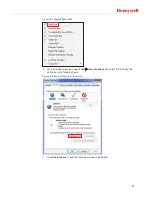
Take Internet Explorer 8 as an example. Right click on the blank space on the top of the 
browser and check the “Menu bar” item in the text menu.


Summary of Contents for HUS-NVR-1032/6032-C

Page 1: ... Document 800 13326 Rev C HUS NVR 1032 6032 E HUS NVR 1032 6032 C 32CH Network Video Recorder User Guide 32 䙊䚃㖁㔌㿶仁ᖅ ۿ ᵪ ᡧ ...

Page 2: ......

Page 3: ...Reserved 11 Intercom Output Reserved 11 Alarm Input Output 12 Specifications of Alarm Input 12 Specifications of Alarm Outputs 12 Specifications of Alarm Output Relay 13 Example of Alarm Input Output Connection 13 Network Connection 13 USB Connection 14 e SATA 14 4 Basic Operations 15 Using the Mouse 15 Turning On 16 Default Accounts 17 Wizard 18 Switch User 23 Change Password 24 Log Off 24 Restar...

Page 4: ...us 59 Hard Disk Status 60 Record Setup 61 Scenario Mode 61 Trigger Profiles 62 Alarm Schedule 64 Alarm Record 65 System Setup 65 General Settings 65 System Settings 66 Display Settings 69 User Settings 70 Network Settings 72 Alarm Settings 75 Storage Settings 77 6 NVR Internet Explorer IE Client 86 System Requirements 86 Internet Explorer Configuration 86 Login 89 Playing Live Video 89 Local Recor...

Page 5: ...6 ࡽ䶒ᶯ 86 㛼䶒ᶯ 87 3 ᆹ㻵о᧕㓯 89 ⴈᆹ㻵 89 㿶仁䗃 ޕ 䗃ࠪ 丣仁䗃 ޕ 䗃ࠪ 90 㿶仁䗃 ޕ 90 㿶仁䗃ࠪ 90 丣仁䗃ࠪ 90 ሩ䇢䗃 ޕ 亴 90 ሩ䇢䗃ࠪ 亴 90 ᣕ䆖䗃 ޕ 䗃ࠪ 91 ᣕ䆖䗃 ޕ 䈤 91 ᣕ䆖䗃ࠪ䈤 91 ᣕ䆖䗃ࠪ㔗 ಘ ᮠ 92 ᣕ䆖䗃 ޕ 䗃ࠪ䘎᧕ᇎֻ 92 㖁㔌䘎᧕ 92 USB ᧕ਓ 93 e SATA 93 4 สᵜ 94 啐ḷ 䈤 94 ᔰᵪ 95 唈䇔 ᡧ 96 ੁሬ 97 ᦒ ᡧ 102 ᇶ 102 䬰 103 䟽 㔏 103 ޣ ᵪ 104 ᚒ Ⓚ 䳌 104 ᴤᦒ 105 ...

Page 6: ... 㿶仁デਓ 127 ḕ䈒 ԭ 129 ḕ䈒㿶仁 129 ԭ㿶仁 130 ḕⴻᰕᘇ 133 ᰕᘇ 133 ᣕ䆖ᰕᘇ 134 㔏 ᘱ 137 สᵜ ᘱ 137 㖁㔌 ᘱ 137 ⴈ ᘱ 139 ᖅ ۿ 䇮㖞 140 ൪Ჟ ᔿ 140 䀖ਁ㿴ࡉ 141 ᣕ䆖䇑ࡂ 143 ᣕ䆖ᖅ ۿ 143 㔏䇮㖞 144 ᑨ 䇮㖞 144 㔏䇮㖞 144 ᱮ 䇮㖞 147 ᡧ䇮㖞 148 㖁㔌䇮㖞 151 ᣕ䆖䇮㖞 154 ᆈۘ䇮㖞 156 6 㖁㔌ᇒᡧㄟ 165 㔏㾱 165 㖁㔌 㿸ಘ䝽㖞 165 ⲫᖅ 167 ᇎᰦ㿶仁 168 ᵜൠᖅ ۿ 169 എ 㿶仁 170 䇮 171 ...

Page 7: ...it to rain or water Situate away from items that produce heat or are heat sources Keep the unit well ventilated Place the unit on a stable flat surface or install it on the rack Do not place any objects on the unit 4 Battery The built in battery life is approximately 2 years as an indication of replacement This is just an indication of replacement We are not providing any guarantee for the built i...

Page 8: ......

Page 9: ...ic configurations and common operations in the system Chapter 5 System Operation and Configuration provides comprehensive and detailed instruction on the system operations Chapter 6 NVR Internet Explorer IE Client introduces how to configure the Internet Explorer and login NVR IE Client Special Fonts and Symbols Italic Indicates referenced chapter figure number page number etc In the electronic ve...

Page 10: ... for future use x The manual has been reviewed and its accuracy is guaranteed If there is any uncertainty or controversy please refer to the final explanation of Honeywell Honeywell does not take any responsibility for any consequences caused by the misunderstanding of the manual or incorrect operations by the user ...

Page 11: ...ailable on all video modes x Supports playback on local machine or IE client x Supports synchronous or independent playback of 4 channels 1080P videos x Supports search and play history videos based on search conditions x Supports multiple operations at the same time recording playback search and back up x Supports various playback speeds and playback frame by frame x Supports displaying the date ...

Page 12: ...control x Play back search and download history videos x Configure system settings and upgrade the firmware from the web client x Handle alarms and view system log remotely x User and password management can prevent unauthorized users from logging into the system Communication Ports x RS485 port Reserved x RS232 port x Alarm input and Alarm output x RJ45 Ethernet port User Interface Operations x W...

Page 13: ...annels 0V 5 0V Alarm Output 4 channels 30VDC 1A Normal Open Normal Close Form C relay Network Interface 2 RJ 45 ports 10 100 1000M Backup USB Device Network download Power Supply 100 240 VAC 50 60Hz Model 1032 12V DC 15A Model 6032 Power Consumption without HDD 50W Operating Temperature 10Ԩ 55Ԩ Storage Temperature 40Ԩ 70Ԩ Humidity 20 80 Dimensions 482mm W x 478mm L x 91mm H Weight Gross weight 11 ...

Page 14: ...box CD 1 Power cord 1 Model1032 Power cord 2 Model6032 Power adapter 2 Model6032 GIGA LAN CABLE 3000mm CAT 5E 1 6 32 1 4 FM 32 M6 12 PB 2 Quality certification 1 Terminal Blocks 4 Quick Guide 1 Desiccant SILICA 1 Remove the protective film on the NVR after the above procedures Operating Keys Front View Figure 2 1 Front View ...

Page 15: ...f the system is starting Blue On the system is running properly Red Flashing system exception 4 ALARM Alarm Indicator Flashes when an alarm occurs 5 REC Recording Indicator On NVR is recording 6 LAN1 Network 1 Indicator Flashes when LAN1 is connected 7 LAN2 Network 2 Indicator Flashes when LAN2 is connected 8 HDD Tray Button Press to open the HDD tray 9 HDD Active Indicator Flashes when HDD is act...

Page 16: ...P 75 ȍ port auxiliary video output 4 AUDIO out1 Real time or playback audio output 5 AUDIO out2 Intercom audio output Reserved 6 MIC in Intercom audio input Reserved 7 ALARM In 16 alarm in ports 8 ALARM Out 4 alarm out ports SPDT Relay 12V DC 12V output 500mA RS485 Reserved 9 USB USB 2 0 for connecting USB devices 10 LAN1 LAN2 Network connection 11 VGA Main video output User interface 12 RS232 Ser...

Page 17: ... 9 15 Grounding Screw For grounding 16 17 Labels MAC address and rating plate 18 Power Alarm Mute Button Turn on off the power alarm sound ...

Page 18: ...you to dangerous voltage or other hazards and damage the unit x Make sure to ground the cabinet of the NVR The grounding screw is on the rear panel of the unit HDD Installation It is recommended that you use SATA II HDDs 500G and above Consult the vendor to get the latest compatible hard disk list 1 Pull out the HDD tray from the NVR 2 Secure the HDD in the tray with the screws provided in the pac...

Page 19: ...ive audio of one channel or playback audio If using a HDMI port a certified HDMI cable should be used It is recommended that you use a 16 9 industrial monitor supports 1080p equipped with HDMI or VGA port as the output device of the NVR Audio Output The audio signal is 3000mVp p 5K ȍ RCA and can be sent to earphones with low impedance active speakers or other audio devices Audio out 1 is for audio...

Page 20: ...rrent 500mA ALARM IN 1 16 16 channels alarm input ALARM OUT1 4 4 channels alarm output NC is the normal close port NO is the normal open port COM is the common port RS485 A B RS485 communication port Reserved Specifications of Alarm Input 1 The 16 alarm inputs can be set to normally open or normally closed independently 2 The COM ports of alarm detectors should connect to the GND of NVR 3 The powe...

Page 21: ... specifications of your own devices Refer to the following figure for the connections of electronic lock alarm indicator and PIR Figure 3 2 Example Alarm Input Output Connection Network Connection The standard RJ45 port makes it convenient to connect the NVR to the network LAN1 and LAN2 are for connecting to other network devices The NVR network is a self adapting 10 100 1000Mb Use the provided ne...

Page 22: ...re the NVR runs properly do not connect USB devices which consume a lot of power e SATA e SATA port is used for connecting SATA disk or specified disk arrays contact the technical support for the model number of HDD array Make sure that the initialization of disk RAID ARRAY has been completed successfully before use Refer to the manual of the disk RAID ARRAY ...

Page 23: ...ove the cursor over the target item then press and hold down the left mouse button to grab the item Move the cursor to the target position and then let go of the mouse button x Double click left button double click the left mouse button in the selected video window to switch to whole window mode and double click the left mouse button again to return to normal window x Operations of buttons checkbo...

Page 24: ...Click to onfirm and close the keyboard Letter lower case Letter upper case Symbol Simplified Chinese x Click letters to input Pinyin and it displays the corresponding Chinese characters x Click to select the target character x Click or to turn the page up or down Turning On Press the Power Switch on the rear panel and the power Indicator on the front panel will turn on the NVR After a while the fo...

Page 25: ...gin Default Accounts There are three default accounts Table 4 2 System Default Users User Name Password Default Authority admin 123456 All operator 12345 View System Status View Alarm Log System Setup Record Setup Wizard Live View Management Front end Device Management and Playback Control guest 1234 View System Status Live View Management and Playback Control ...

Page 26: ...adding devices etc When the Wizard is completed the NVR could start working properly To start Wizard do the following 1 Enter the user name and password on the login screen and click the Wizard button to go to the User tab as shown in the following figure Figure 4 4 User 2 The current user s password can be changed on the above tab Click Next to go to the Date Time tab as shown in the following fi...

Page 27: ... 6 Obtain an IP address automatically 4 You can set IP address for the NVR on this tab If select Use the following IP address for LAN 1 you should manually set IP Address Subnet Mask and Gateway respectively as shown in the following figure the below figure will change based on your DHCP settings Figure 4 7 Set the IP address manually ...

Page 28: ...configuration take effect immediately Click Next to go to the Storage tab as shown in the following figure Figure 4 8 Storage 6 To format the selected disk click Initialization Click Next to go to Devices tab as shown in the following figure Figure 4 9 Devices ...

Page 29: ...nd save the file into USBˈ and then connect the USB to the NVR and the Import File window is displayed as shown in the following figure Figure 4 10 Import File b After selecting the target file on the above window click Import and click Next to go to Result of Import window as shown in the following figure Figure 4 11 Result of Import ...

Page 30: ...he following figure Figure 4 12 Recording Scenario d You can select Record with high quality or Record with standard quality on the above window Click Next to go to Done tab 7 The Done tab displays the configuration results as shown in the following figure To modify any configuration click Back to return to the target tab Figure 4 13 Done ...

Page 31: ...exit the wizard and display the Live screen as shown in the following figure Figure 4 14 Live Screen First Login Switch User To switch to another user navigate to ÆSwitch User in the top left corner of Live screen and click OK in the pop up window as shown in the following figure Figure 4 15 Switch User ...

Page 32: ...een and a window is displayed as shown in the following figure Figure 4 16 Change Password Input old password new password and confirm password and then click OK Log Off To log off the system navigate to ÆLog Off in the top left corner of the Live screen and click OK in the pop up window as shown in the following figure Figure 4 17 Log Off ...

Page 33: ...tdown the system navigate to ÆShutdown in the top left corner of the Live screen and click OK in the pop up window as shown in the following figure or hold down the ON OFF switch for over 5 seconds on the front panel of the NVR this method is not recommended for data loss may occur Figure 4 19 Shutdown Recovery Power Failure If the NVR crashes restart the machine to resume the working condition If...

Page 34: ...mmended that the Lithium batteries should be replaced with the same battery type To ensure the accuracy of the system time replace the Lithium battery every two years Replace the battery when the NVR is powered off and then reset the system time after restarting it ...

Page 35: ...deo check alarm log switch layout and scenario manage cameras and disks record manually control PTZ etc To play the live video drag the target camera icon from the Devices list to the target video window The Live screen is displayed as shown in the following figure Figure 5 1 Live Screen After successfully logged in all the connected cameras start scheduled recording by default To stop or set the ...

Page 36: ... screen Refer to the System Status section on page 58 Record Setup Enter the Record Setup screen Refer to the Record Setup section on page 61 System Setup Enter the System Setup screen Refer to the System Setup section on page 65 Change Password Change the current user s password Refer to the Change Password section on page 24 Switch User Switch to another user Refer to the Switch User section on ...

Page 37: ...up menu The Instant Playback supports 4 windows at most at the same time In addition the total decoding ability of Live video and Instant Playback can not exceed 4 x 1080P Stop Playing the Live Video Right click the video window and select Stop Playing in the pop up menu Aspect Ratio Right click the video window and select Change the Aspect Ratio in the pop up menu Switch Stream Right click the vi...

Page 38: ...e related live groups You can create views to switch among different live video groups There are up to 16 live videos in a view and the created views are listed in the right Views list To play a view drag a view icon from the Views list to the video window The Views list is as shown in the following figure Figure 5 3 Views List Creating a View 1 Select a layout from the Window layout 2 Drag the ta...

Page 39: ...uth Square from the Views list to the video window and then click in the bottom right corner of the Views list to enter the editing mode as shown in the following figure Figure 5 5 Editing Mode Refer to step 1 and 2 of Creating a View on page 30 to edit To give up editing click When editing is done click in the bottom right corner of the window and a pop up window is displayed as shown in the foll...

Page 40: ...dow is displayed click OK Device Operation The Devices list is on the right side of the Live screen and displays the IP cameras connected to this NVR In the Devices list you can add edit configure and remove the camera or play the live video record manually and play history video Device name in blueüonline Device name in redüan alarm is occurring and the icon is displayed Device name in greyüoff l...

Page 41: ...taining parameters of cameras to the NVR Add Click Add tab in Add Devices window and then select Device Type and input the IP Address Port User Password and Camera Name as shown in the following figure Figure 5 8 Add Camera If you choose Honeywell 4 Channel Streamer HUSS E4V in Device Type you need to select the camera 1 4 from the below Camera dropdown list If you want to set stream PTZ and multi...

Page 42: ...elect camera s type from the dropdown list as shown in the following figure Figure 5 10 Search Camera 2 Click Search and then all the cameras of this type are listed Click to turn page down 3 Check the target camera checkbox Click Quick Add when the pop up window is displayed click OK to add the selected cameras to the Devices list or click Next to manually edit the parameters see Figure 5 8 ...

Page 43: ...le cvs on it to the NVR 2 Click Import tab on Add Devices screen as shown in the following figure Figure 5 11 Import Devices List 3 Click Import devices list and the Import File window is displayed as shown in the following figure Figure 5 12 Import File ...

Page 44: ...ameras 5 Check the target camera and click to turn page down 6 Click Add when the pop up window is displayed click OK to add target cameras to the Devices list Editing a Camera Select a camera in the Devices list Figure 5 7 and click in the bottom right corner and the following screen is displayed You can modify the camera s access parameters on this screen Figure 5 14 Editing a Camera ...

Page 45: ... in the above window and the Advanced Settings window is displayed as shown in the following figure Figure 5 15 Advanced Settings After the settings are finished click OK and the following pop up window is displayed Figure 5 16 Success Click OK to close the window and exit ...

Page 46: ... and then right click the icon of the target camera in the Devices list and select Live in the pop up menu x Drag the icon of the target camera to the designated video window Play back Video Select a video window on the Live screen and then right click the icon of the target camera in the Devices list and select Playback in the pop up menu Manual Recording On the Live screen you can manually start...

Page 47: ... hold down it again for over 1 second to stop recording Storage The Storage list displays the disk information Disk 01 08 indicate the corresponding disks and e SATA indicates the optional e SATA disks For Model 1032 click on the left of Disk xx to view detailed information including total size free space R W type status and channels as shown in the following figure Figure 5 18 Storage Model 1032 ...

Page 48: ...ing of Virtual Disk refer to Storage Settings on page 77 To refresh the disk information click Read Write Type x To set a disk to READ ONLY right click the disk icon and select SetÆRead Only x To set a disk to READ WRITE right click the disk icon and select SetÆRead Write Ejecting Disk To remove a disk from the NVR right click the disk icon and select Eject in the pop up menu and the below window ...

Page 49: ...e disk during system start up x It is recommended that to eject the disk by user interface operation otherwise it will damage the disk or cause data loss x It is recommended that the ejection interval between two disks is not less than 30 seconds Formatting Disk To format a disk right click the disk icon and select Format in the pop up menu and then a pop up window is displayed Figure 5 22 Format ...

Page 50: ...llowing figure Please consult technicians Figure 5 23 S M A R T Information Click OK to close the window Viewing Properties To view the disk properties right click the disk icon and select Properties in the pop up menu The information will be displayed in a window as shown in the following figure Figure 5 24 Properties S M A R T Evaluation has two indexes Pass Failed Whole Evaluation has three ind...

Page 51: ...on of the target camera is changed to 2 Drag the target camera icon from the Device list to the video window 3 Move the cursor to the bottom of the current video window and the hidden PTZ control bar is displayed as shown in the following figure Figure 5 25 PTZ Control Bar Click to display the control interface as shown in the following figure Figure 5 26 PTZ Control Interface Figure 5 27 PTZ Cont...

Page 52: ...age Click to select Save Preset and click to choose a numeric figure in the box Click Save Go To Preset Figure 5 29 Go To Preset To turn the camera to an existing preset click to select Go to Preset and click to choose the target numeric figure in the box Click Go Click to exit PTZ control Patrol Patrol function can circularly play groups of live videos Click ÆConfiguration on the Live screen and ...

Page 53: ...he above window and the New Slide window is displayed as shown in the following figure Figure 5 31 New Slide 2 Enter the Slide Name in the text box and click OK The Edit window is displayed as shown in the following figure Figure 5 32 Edit Patrol ...

Page 54: ...lick Save to create the patrol in the Patrol List window Figure 5 30 Editing a Patrol To edit a patrol select a patrol in the Patrol List Figure 5 30 and click Edit to enter the edit window Figure 5 32 Refer to step 3 and 4 of Creating a Patrol to edit a patrol Remove Patrol To remove a patrol select a patrol in the Patrol List Figure 5 30 and click Remove Preview Patrol To preview a patrol select...

Page 55: ...own list Click to enter the patrol mode as shown in the following figure Figure 5 35 Play Patrol Click to pause playing and click to stop playing and exit the patrol mode To play patrol in full screen mode first click icon and then click to select the target patrol in the list click icon to play ...

Page 56: ...o play back video drag the icon of the target camera from the Devices list to the video window or click the icon in the video window to select the target camera from the pop up list The default start time of playback is 12 00 am Synchronous Playback To control the four windows using the playback control from a same point of time click at the left top corner of the screen to enter the synchronous p...

Page 57: ...Display the time scale Video Strip The video strip with different colors represents different types of video greenüscheduled recording blueümanual recording yellowüvideo event redüalarm recording Drag the video strip to select the video start time that the axis indicates Axis The playback time of video The date and time is displayed below which can be clicked to expand the calendar and the date in...

Page 58: ...ore to the normal speed Previous Frame When paused click to go to the previous frame Next Frame When paused click to go to the next frame Speed Display the current play speed 1x represents the normal speed Filter To filter videos on the Playback screen specify the target time and event type in the Filter window as shown in the following figure Figure 5 38 Filter Click Default to select All Events ...

Page 59: ...e Filter window and the target video is displayed as shown in the below figure Figure 5 40 Seach Result 3 Select and drag the target video strip marked with white dashed line to specify the playback start time The Preview window displays the image you select as shown in the below figure Figure 5 41 Preview 4 Click Playback in the Preview window Figure 5 41 to skip to the Playback screen to play ba...

Page 60: ...t cameras Right click the yellow area and select Add to backup list in the pop up menu then the target camera with selected period of time will be added to the Backup List on the left as shown in the following figure Repeat the steps to add other cameras with other periods to the backup list Figure 5 42 Back Up Video 3 Click Show Size in the bottom left corner of the screen See Figure 5 39 Search ...

Page 61: ...the Playback screen 1 Drag the camera icon to the video window 2 Drag on the timeline marked with red box to specify the time period to be backed up in yellow as shown in the following figure Figure 5 44 Back Up Video on Playback Screen 3 Right click the selected area in yellow select Add to backup list in the pop up menu and then the following window is displayed Figure 5 45 Export Video Clips on...

Page 62: ...iece of logs respectively Operation Log To view the Operation Log navigate to ÆView LogÆOperation Log on the Live screen and the following screen is displayed Figure 5 46 Operation Log Click to turn to the next page click to skip to the last page To skip to the designated page click the cursor in the text box and scroll the mouse wheel to select the target page number and click Go Check the Date T...

Page 63: ...arm Log window The unread logs are in orange and the read ones are in black as shown in the following figure Figure 5 47 Alarm Log Click on an unread log and the figure below is displayed Figure 5 48 Log Expanded Click to play the live video of the related camera click to play back the recorded video of the related camera Click in the top right corner of Alarm Log window Figure 5 47 the sub menu i...

Page 64: ...the System Alarm section on page 76 Select Export to export the target log to the external USB device or click Remove All and the below window is displayed Figure 5 50 Remove All Alarm Log Click OK to remove all alarm log Input Alarm Log Navigate to ÆView LogÆAlarm LogÆInput Alarm Log on the Live screen to view the input alarm log as shown in the following figure ...

Page 65: ... Time in the top left corner to select the target date to be viewed in the pop up calendar click All to select the target type in the dropdown list Click Backup to back up the entire log to the external USB device or click Remove to delete the entire log System Alarm Log Navigate to ÆView LogÆAlarm LogÆSystem Alarm Log on the Live screen to view the system alarm log as shown in the following figur...

Page 66: ...p left corner to select the target date to be viewed in the pop up calendar click All to select the target type in the dropdown list Click Backup to back up the entire log to the external USB device or click Remove to delete the entire log System Status To view the performance status of the running system navigate to ÆSystem Status Basic Status The Basic Status window is displayed by default as sh...

Page 67: ...hen below window is displayed Figure 5 54 Nerwork Status Click Receiving in the above window to view the parameters of data being received and click Transmitting right next to Receiving button to view the parameters of data being sent Figure 5 55 Receiving Sending Chart ...

Page 68: ... Ms Figure 5 56 Bit Rate Chart In the above window the column with grey writing represents the camera and the column with yellow writing represents the bitrate of the camera Kbps Hard Disk Status Click on the Hard Disk Status column and the following window is displayed Figure 5 57 Hard Disk Status Click the S M A R T column for details ...

Page 69: ...der My favorite scenario mode there are three scenarios for selection Working day scenario Holiday scenario and My favorite scenario as shown in the following figure Figure 5 58 Select Scenario Mode This screen contains the following settings High quality recording enables main stream recording to ensure high resolution image but with larger size Standard quality recording enables auxiliary stream...

Page 70: ... Off Cancel the schedule 2 Click on the corresponding square or drag an area and select High Quality Low Quality Off in the popped up menu as the figure below Figure 5 60 Recording Mode Selection The green square in the above figure represents the selected camera will start recording with standard quality mode at 5 30 6 00 on Sunday Replicate this method to set the other cameras When finished clic...

Page 71: ...5 62 Add Alarm Device and Triggered Device 4 Configure the added device in Camera Settings window To remove a device select that row and click Remove as shown in the following figure Figure 5 63 Camera Settings 5 Configure Alarm Output Show Message and Audible Alarm in System Settings window as the figure below Figure 5 64 System Settings 6 Set Pre Recording and Post Recording Pre Recording starts...

Page 72: ...gure 5 65 refer to New Profile operation Remove To remove a profile select it and click Remove in Alarm Profile list Figure 5 65 Alarm Schedule After the alarm rules are compeleted you can set up the video schedule for devices Click ÆRecord SetupÆAlarm Schedule the following window is displayed Figure 5 66 Alarm Schedule The blue blocks indicate the video is enabled the grey blocks indicate the vi...

Page 73: ...column High Quality Standard Quality The Alarm schedule or the Alarm Record is one of the Trigger Profiles and both can be set up to form the trigger profiles System Setup This section describes the settings and related operations General Settings Navigate to ÆSystem SetupÆGeneral Settings and the below figure is displayed Figure 5 68 General Settings ...

Page 74: ...ns Date and Time Audio System Management and System Information as shown in the following figure Figure 5 69 System Settings Date and Time Click the Date and Time and the below window is displayed Figure 5 70 Date and Time In the above window you can set time zone date time and whether to synchronize with NTP automatically Click Advanced Settings and the below window is displayed Figure 5 71 Advan...

Page 75: ...4 System Management You can upgrade firmware restore to factory default settings export import configuration file and enable auto log off Upgrade Firmware Steps 1 Copy the upgrade file hdu file into a USB storage device and connect it to NVR Click Upgrade Firmware in the window above 2 In the pop up window select the upgrade file and click OK It will display the version information of the current ...

Page 76: ... exporting the configuration file Config_export hdc and wait until it shows that the exporting is complete Import Configuration File To import a configuration file copy the configuration file hdc file into a USB storage device and connect it to the NVR Click Import as shown in Figure 5 74 and the below window is displayed Figure 5 76 Import Select the target file and then click OK to start importi...

Page 77: ...tem Information Display Settings Click Display Settings in Figure 5 68 to enter the Display Settings screen and where there are 3 options Basic Image and Patrol as shown in the figure below Figure 5 78 Display Settings Basic Click Basic to view and modify User Interface language resolution and Local On screen Display as shown in the following figure Figure 5 79 Display ...

Page 78: ...tion on page 44 User Settings Click User Settings in Figure 5 68 to enter the User Settings screen and where there are 2 options User Management and Role Authority as shown in the following figure Figure 5 81 User Settings User Management Click User Management to view the basic information of current selected user reset password etc as shown in the following figure Figure 5 82 User Management ...

Page 79: ...ser x The NVR supports a maximum of 32 users If a message pops up indicating that the maximum number of users has been reached you cannot create any new users You will need to delete users before adding new ones Edit User To edit a user click Edit in the User List window Figure 5 82 and the Edit window is displayed Figure 5 84 Edit You can modify the Role in the above window Remove User To remove ...

Page 80: ...y Click Role Authority to check and set authorities of Operator and Guest users Admin user can not be edited Figure 5 85 Role Authority Only Administrator user is able to manage role authority options Network Settings Click Network Settings in Figure 5 68 to enter the Network Settings screen and where it includes Basic Multicast and Email as shown in the following figure Figure 5 86 Network Settin...

Page 81: ... 73 Basic Click Basic and the below window is displayed Figure 5 87 Network Basic Settings This screen contains the following items Standalone set LAN1 and LAN2 seperately Figure 5 88 Standalone ...

Page 82: ...CP server Click Save and it displays IP Address Subnet Mask Gateway and DNS values after a few seconds Make sure NVR has access to the DHCP server which is running on the Ethernet network Use the following IP adress Select it to allow user to configure IP address Subnet Mask Gateway and DNS manually Default Route Set the route for the device Max User s Specify the maximum number of simultaneously ...

Page 83: ...Click the tab of Email and the following window is displayed Open Close Email reminder and make relative settings in this window After that click Test and the testing result will be shown on the right Figure 5 92 Email Alarm Settings Click Alarm Settings in Figure 5 68 to enter the Alarm Settings screen and where there are 3 options System Alarm Alarm Output and Alarm Input as shown in the followi...

Page 84: ...arm to set Alarm Output Show Message and Audible Alarm when related events ocurr Figure 5 94 System Alarm Alarm Output Click Alarm Output to set Trigger Type and Duration as the figure below Figure 5 95 Alarm Output Alarm Input Click Alarm Input to set the alarm input status as the figure below ...

Page 85: ...ick the tab of Storage Settings in Figure 5 68 General Settings the following window is displayed Note Model 6032 has RAID and Storage while Model 1032 has only Storage Figure 5 97 Storage Settings Model 6032 Figure 5 98 Storage Settings Model 1032 ...

Page 86: ...ith the same type should be used Quicly Create RAID existed only when the RAID list is empty 1 Click Quicly Create RAID in the RAID window and the followling window is displayed Figure 5 100 Quickly Create RAID 2 This operation quickly creates RAID according to the current disk status Input the name of RAID and click OK then the new RAID will be listed in the RAID window as shown below ...

Page 87: ...indow Add RAID When the first RAID is created the RAID window will be different from the original one and an Add button appeared as shown in Figure 5 101 Click Add and the window of Manually Create RAID is popped up Refer to Manually Create RAID for detailed operations DŽ Manually Rebuild Only when the status of the RAID is Degrade the RAID can be manually rebuilt To manually rebuild a RAID you mus...

Page 88: ...o a RAID cannot be selected and click OK then the RAID can be used normally Edit the Global Hot Spare 1 Click Edit the Global Hot Spare the following window is displayed Figure 5 104 Edit the Global Hot Spare 2 Select one or more disks that are not auxiliary to any RAID as a global hot spare as shown below ...

Page 89: ... Hot Spare Editing Done Auto Rebuild If checked the box before Auto Rebuild the program will automatically rebuild the RAID using the hot spare when the disk of a RAID breaks down Edit RAID To edit a RAID select the target RAID in the RAID list and click Edit then the following window is displayed Figure 5 107 Edit RAID ...

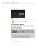
Page 90: ...rase all the data on it Storage Management Model 6032 Note A corresponding virtual disk will be automatically generated after a new RAID is built Click the tab of Storage Mgmt and the following window is displayed including all physical disks excl RAID disk and virtual disks Figure 5 109 List of Storage Model 6032 Configuration Take configuring the virtual disk as example 1 Select the target virtu...

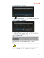
Page 91: ... will tell if the configuration succeeded If succedded click OK to return to the list of Storage The following window displayed the informaiton of the newly configured virtual disk Figure 5 112 Configuration Done Configure other storage devices disk or eSATA according to the above steps Combine To perform the operation of Combine you must choose the virtual disks with the same RAID type 1 Select t...

Page 92: ...Virtual Disk 3 Input the name of the new virtual disk and click OK then the following window is displayed Figure 5 115 Warning 4 Click OK and a pop up window will tell if the operation is successful If suceeded click OK to return to the list of Storage and the information of the combined virtual disks is displayed in the list as shown below ...

Page 93: ...ge Management Model 1032 Click the tab of Storage Mgmt and the following window is displayed Figure 5 117 List of Storage Model 1032 All the physical disks can be configured in this window Refer to Model 6032 for detailed configurations ...

Page 94: ...e System Requirements x CPU Intel i5 750 2 66 GHz x System Memory 4 GB x Optical Drive DVD R x HDD 250GˈEnsure 20G available space x Network Interface Card 1000Mbps Dual or compatible pair of NICs x Keyborad 102 key keyboard and a mouse pointing device x Graphics Adapter NVIDIA 1GB Independent Graphic Card x Operating System Window 7 Professional 32 bit Window 7 Enterprise 32 bit Internet Explorer...

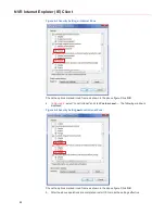
Page 95: ...ay Menu Bar 2 On the browser menu bar open ToolsÆInternet options and select the Security tab as shown in the following figure Figure 6 2 Internet Options Security 3 Click Custom Level and the following window is displayed ...

Page 96: ...the above figure Click OK 4 In Figure 6 2 select Local Intranet and click Custom Level The following window is displayed Figure 6 4 Security SettingsüLocal Intranet Zone Check the options marked in red frame as shown in the above figure Click OK 5 After the above operations are completed restart IE to make the settings effective ...

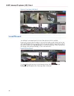
Page 97: ...is displayed Figure 6 6 Login Select the user name and enter the password Click Login When successfully logged in the Live screen is displayed Playing Live Video Follow one of the operations below to play live video x Drag the target camera icon from the Devices list to the target video window x Click the icon in the video window to select the target camera from the pop up list x Right click a cam...

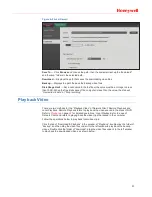
Page 98: ...w right click the window and click Local Record in the pop up window then the computer starts to download the video to the computer disks click Local Record again it will stop downloading When downloading the top right of the window will display Local as shown below Figure 6 8 Local Record The downloading path can be set in the following window Click ÆLocal SettingsÆLocal Record and the following ...

Page 99: ...e two methods for the Playback Video of Network Client Remote Playback and Local Playback Remote Playback refers to play back the videos saved in the disks of NVR Refer to Playback on page 48 for detailed operations Local Playback is for the use of Network Client and refers to playing back the video clips that saved in the computer Follow the operations below to play back local video clips Click t...

Page 100: ...is displayed Figure 6 11 Device Management On the left of this window users can add edit and delete one or more NVRs Click the name of the NVR and the name and IP of its cameras are displayed on the right The operations of adding editing and deleting NVR are the same to those of IP Camera For detailed operations refer to Adding a Camera on page 33 Note In the window of adding and editing NVR users...

Page 101: ... 93 Figure 6 12 Advanced Settings ...

Reviews: