HUVF SERIES DUCT MOUNTED UV SYSTEM
3
31-00455—01
PLANNING THE
INSTALLATION
NOTICE:
• Read the maintenance instructions before opening the
appliance.
• Appliances that are obviously damaged must not be
operated.
• UV-C BARRIERS bearing the ULTRAVIOLET RADIATION
hazard symbol should not be removed.
• Do not operate UV-C LAMPS outside of the appliance.
Choosing a Mounting Position
CAUTION
Equipment Damage Hazard.
Ultraviolet light can cause color shift or surface
degradation and sometimes structural degradation
of non-metallic components. Select mounting
location that prevents exposure to plastic flexible
duct components, polyurethane foam insulation
material, rubber hoses, wire insulation, etc. If
mounting options are limited, items above should
be protected with ultraviolet resistant material such
as aluminum foil, aluminum duct tape, or metallic
shields or the equivalent.
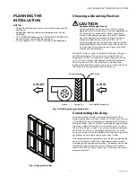
The HUVF Series is used in forced air heating, cooling, or
ventilating systems. The system is mounted in the air
handling unit (AHU) or ductwork where there are cooling
coils or other surfaces that require ultraviolet treatment.
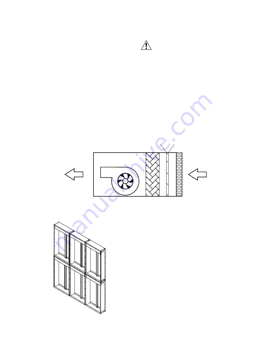
When used in an AHU, the installation shall be done
between the pre-filters and cooling coil in such a way that
the lamps are facing towards the cooling coil.
Fig. 3. HUVF positioning inside AHU.
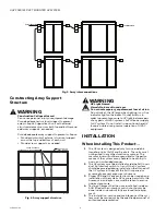
Fig. 4. Array detail view.
Constructing the Array
Multiple systems can be nut and bolted to each other,
either side by side or on top of other, to fill the cross section
of the ductwork or air-handling unit where the UV system is
being installed. If each system is individually supported by
the array support structure it is not necessary to connect
the systems to each other. The system can be connected to
each other as shown in the diagram below. Two or more
systems can be connected side by side, and when required
multiple rows can be placed on top of each other.
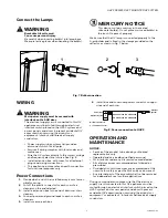
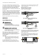
The male and female connectors are used for powering the
systems. A common 230 Vac single phase power source
shall be used for powering the array. The power shall not be
turned 'ON' until all the mechanical fitment is finished,
refer to WIRING section at the end of installation for mains
power connection.
AIR OUT
Detail Arrangement
AIR IN
HUVF Series
Blower
Cooling Coil
Pre Filter/F58 Series EAC

