HVAC400X – APPLICATION MANUAL
EN2B-0417GE51 R0719
20
3.2
Using the HMI
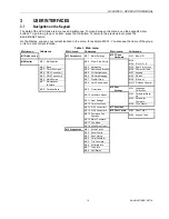
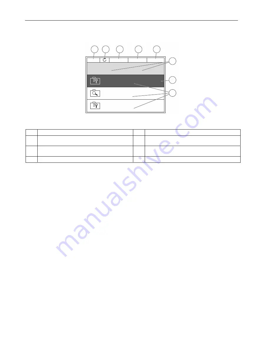
Fig. 8. The basic menu structure of the HVAC drive
Legend
A.
The first status field: STOP/RUN.
E.
The control place: PC / IO / KEYPAD / FIELDBUS.
B.
The rotation direction.
F.
The location field: the parameter ID number and the
current location in the menu.
C.
The second status field: READY / NOT READY /
FAULT.
G.
An activated group or item: press OK to enter.
D.
The alarm field: ALARM/-.
H.
The number of items in the group in question.
STOP
READY
I/O
Main Menu
M1
ID:
Quick Setup
( 17 )
Monitor
( 5 )
Parameters
( 12 )
B
C
D
E
A
F
G
H


