background image

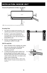
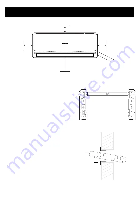
Clearance Requirements for Indoor Installation

INSTALLATION: INDOOR UNIT

10

5.9 in

7.9 in

7.9 in

78.7 in

NOTE

: All measurements should be no less than posted from obstructions.  

Mounting Plate

1. The wall for installation of the indoor unit 

shall be hard and firm to prevent vibration.

2. Use the “+” type screw to fasten the 

mounting plate. Horizontally mount the 

mounting plate on the wall and ensure it is 

level with the wall.

3. Pull the mounting plate by hand after 

installing to confirm if it is solid.

Wall-Through Hole

1. Make a 60-80mm hole as appropriate, where 

there are no obstructions for drilling. The 

indoor connection pipe should slant 

outwardly by 10-20

°

.

2. To protect the piping and the cables from 

being damaged running through the wall, 

the pipe protecting ring shall be installed and 

sealed with the putty that is included on the 

inside wall of the dwelling.

NOTE: 

Usually, the wall hole is 60mm ~ 80mm. Avoid 

wiring and studs to maintain structural integrity of the 

enclosure.

Indoor

Outdoor

Pipe

Protection

Ring

Summary of Contents for HWAC-1217S

Page 1: ...HWAC 1217S HWAC 1817S HWAC 2417S Professional Installation Required Please read and retain these instructions Mini Split Air Conditioner Single Zone Installation and Operations Manual ...

Page 2: ...HWAC 1817S or HWAC 2417S Mini Split Air Conditioner This manual will provide you with safety information installation steps instructions for optimal use and proper care and maintenance for your product Please read this manual carefully before operating ...

Page 3: ...dB Indoor Unit 46 dB Outdoor Unit 55 dB Indoor Unit 49 dB Outdoor Unit 55 dB Ambient Range 61 F 90 F 61 F 90 F 61 F 90 F Refrigerant R410a R410a R410a Cord Length 14 8 ft 4 5 m 14 8 ft 4 5 m 14 8 ft 4 5 m Zone Capacity Single Single Single Indoor Unit Dimensions W x D x H 34 68 W x 8 07 D x 11 65 H 35 40 W x 8 90 D x 12 2 H 42 6 W x 9 17 D x 12 99 H Outdoor Unit Dimensions W x D x H 28 74 W x 11 2...

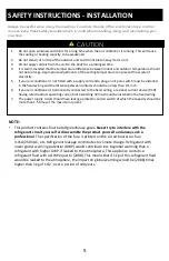
Page 4: ...es 9 Always switch off the device and cut the power supply before performing any maintenance or cleaning 10 Do not yank on the power cable to unplug 11 An earth leakage breaker with rated capacity must be installed 12 Do not install the air conditioner in a place where there is flammable gas or liquid The distance between them should be more than 4 5 ft 13 Do not use air conditioner in stormy weat...

Page 5: ... over a period of 100 years 1 Do not open windows and doors for a long time when the air conditioner is running This will cause the cooling or heating capacity to be weakened 2 Do not stand sit on top of the outdoor unit and do not place heavy items on it 3 Do not apply cold air from the unit to the body for a prolonged time 4 It is recommended that the temperature difference between indoor and ou...

Page 6: ...uvre 5 Air Vent 6 Force Switch 7 Pipe Protector Ring Indoor Unit Open view Outdoor Unit PRODUCT VIEW 1 2 3 4 5 7 1 2 3 4 1 Air Outlet Grille 2 Power Cable 3 Connecting Pipe 4 Drain Hose Outlet Pipe 6 6 1 2 3 4 12k and 24k BTU Version 18k BTU Version ...

Page 7: ...ind direct sunshine or high temperature heat sources Avoid places within the reach of children Allow for a short connection between the indoor and outdoor units Select where it is easy to perform service and repair also where ventilation is good The outdoor unit shall not be installed in any way that could occupy an aisle stairway exit fire escape catwalk or any other public area The outdoor unit ...

Page 8: ...onnection Cable types Outdoor Power Cable H07RN F or H05RN F Interconnection Cord H07RN F or H05RN F Minimum Cross Sectional Area of Power Cable and Interconnection Cord The size of the interconnection cord power cable fuse and switch needed is determined by the maximum current of the unit The maximum current is indicated on the nameplate located on the side panel of the unit Refer to this namepla...

Page 9: ...or a circuit poorly grounded to the earth The grounding wire is specially designed and shall not be used for other purpose nor shall it be fastened with a common tapping screw Others The connection method of the air conditioner and the power cord and the interconnection method of each independent element shall be subject to the wiring diagram affixed to the machine Packing List NOTICE FOR INSTALLA...

Page 10: ... with the wall 3 Pull the mounting plate by hand after installing to confirm if it is solid Wall Through Hole 1 Make a 60 80mm hole as appropriate where there are no obstructions for drilling The indoor connection pipe should slant outwardly by 10 20 2 To protect the piping and the cables from being damaged running through the wall the pipe protecting ring shall be installed and sealed with the pu...

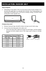
Page 11: ... opposite side Drainpipe Connection 1 Remove the mountings and pull the indoor unit pipe out of the housing 2 Connect the connecting pipe to the indoor unit Aim at the pipe center tighten the taper nut with fingers and then tighten the taper nut with a torque wrench The torque used is shown on the table below INSTALLATION INDOOR UNIT 11 Pipe Size Torque 1 4 15 25 3 8 35 40 1 2 45 60 5 8 73 78 3 4 ...

Page 12: ...drain hose straight 3 Use plastic cable ties to wrap the connecting pipes cables and drain hose Run the pipe sloping downward Fixing the Indoor Unit 1 Hang the indoor unit on the peg board and move the unit from left to right to ensure that the hook is properly positioned in the peg board 2 Push toward the lower left side and the upper right side of the unit toward the peg board until the hook is ...

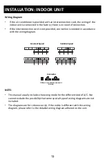
Page 13: ...E This manual usually includes the wiring mode for the different kind of A C We cannot exclude the possibility that some special type of wiring diagrams are not included The diagrams are for reference only If the entity is different with this wiring diagram please refer to the detailed wiring diagram adhered on the unit INSTALLATION INDOOR UNIT 13 Constant Speed Variable Speed Connector If there i...

Page 14: ...sed NOTE This table is for reference only INSTALLATION OUTDOOR UNIT 14 Piping Length 16 4ft CC 12000 BTU 20g m CC 18000 BTU 30g m 16 4ft 49 2ft Not Needed Amount of Refrigerant to be Added Stop Valve Taper Nut Connecting Pipe Spanner Gas Side Pipe Liquid Side Pipe W1 W2 A B NOTE All measurements should be no less than posted from obstructions 11 8 in 7 9 in 11 8 in NOTE Technique to measure distan...

Page 15: ...he cables to the corresponding terminals of the terminal board of the outdoor unit see the wiring diagram and if there are signals connected to the plug just create a butt joint 3 Ground Wire Remove the grounding screw out of the electric bracket cover the grounding wire end onto the grounding screw and screw it into the grounding hole 4 Fix the cable reliably with fasteners Pressing board 5 Put t...

Page 16: ...he vacuum for at least 15 minutes Check that the compound vacuum gauge reads 0 1 Mpa 76cmHg 4 After applying the vacuum fully open the stop valve with a hex wrench 5 Check that both indoor and outdoor connections are free of air leakage INSTALLATION OUTDOOR UNIT 16 Loosen the temporarily fastened nut by half a turn Loosen the Hex wrench by half a turn Wait for 8 seconds Quickly tighten and connect...

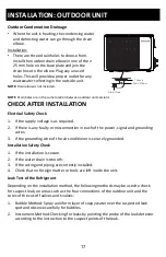
Page 17: ...tallation Safety Check 1 If the installation is secure 2 If the water drain is smooth 3 If the wiring and piping are correctly installed 4 Check that no foreign matter or tools are left inside the unit Leak Test of the Refrigerant Depending on the installation method the following methods may be used to check for suspect leak on areas such as the four connections of the outdoor unit and the cores ...

Page 18: ...er cooling to prevent expelling cold air When it is cold and wet outside the outdoor unit will develop frost over the heat exchanger which will compromise the heating capacity This is when the air conditioner will start to defrost During defrost the air conditioner will stop heating for about 5 12 minutes Vapor may come out from the outdoor unit during defrost This is not a malfunction but a resul...

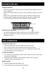
Page 19: ...direction Refer to the operation manual of the remote controller for details NOTICES FOR USE 19 Test Operation Preparation Verify that all piping and connection cables are well connected Confirm that the values at the gas side the liquid side are fully open Connect the power cord of the outdoor unit to an independent power socket Install the batteries in the remote control Test Operation Method 1 ...

Page 20: ...ctly to the sunlight or excessive heat 4 If the remote controller does not work normally remove the batteries for 30 seconds before you reinstall them If that doesn t work replace the batteries 5 When replacing the batteries do not mix new batteries with old ones or mix batteries of different types 6 If the remote controller is not used for a long period of time remove the batteries first to avoid...

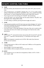
Page 21: ...set the temperature display to Fahrenheit which is displayed by default in Celsius The C will not be displayed on the LCD Press this button again to restore the temperature display to Celsius 3 SPEED Press this button you can select the fan speed as follows Low Mid High Auto NOTE AUTO air speed is not available in FAN mode REMOTE CONTROL FUNCTIONS 1 2 3 4 5 6 7 8 9 10 11 12 13 14 15 21 NOTE The re...

Page 22: ...unit will automatically clean dust off the evaporator and dry it This will increase the cooling and heating efficiency The Clean function runs for approximately 30 minutes if the unit is turned on with the remote controller or this button is pressed again the Clean function will be deactivated Each time the is pressed the temperature setting will increase by 1 F and each time the is pressed it wil...

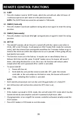
Page 23: ...function is not set in the factory It may be set or cancelled any time as follows With the unit ON press Anti M button once the buzzer will sound 5 times indicating this function is set Once set this function will remain active except when the unit is powered off or until it is cancelled To cancel Anti M 1 Power off the unit 2 With both the unit and the remote controller OFF point the remote contr...

Page 24: ...ts to operate 4 Press the ON OFF button again the air conditioner stops NOTE In the fan operation mode the temperature settings is non effective Cooling Heating Operation Mode 1 Press the MODE button select the Cooling or Heating operation mode 2 By pressing the or button you can set the temperature The display changes as you press the button 3 By pressing the SPEED button you can select the fan s...

Page 25: ...t the drying operation mode 2 By pressing the or button you can set the temperature the display changes as you touch the button 3 By pressing the SPEED button you can select the fan speed from LOW MID HIGH AUTO 4 Press the ON OFF button the air conditioner starts to operate 5 Press the ON OFF button again the air conditioner stops Backlight Function The remote controller has a backlight which can ...

Page 26: ... of the air conditioner with a soft dry cloth or a damp cloth moistened with a gentle detergent Cleaning the Indoor Unit Panel 1 When the panel of the indoor unit is contaminated clean it gently with a wrung towel using warm water below 113 F and do not remove the panel while cleaning Clean the Air Filter 1 Use both hands to open the panel upwards towards the ceiling 2 Release the air filter from ...

Page 27: ...cian Maintain After Use 1 Cut off the power source of the air conditioner turn off the circuit breaker and remove the batteries from the remote control 2 Clean the filter and the unit body 3 Remove the dust and debris from the outdoor unit 4 Check whether there is damage in the mounting bracket of the outdoor unit and if any please contact a qualified service technician Immediately stop all operat...

Page 28: ...peration for 3 to 5 minutes There is an unusual smell blowing from the outlet after operation is started The air conditioner itself does not have undesirable odor If there is odor it may be due to accumulation of the odor in the environment Please clean the air filter or activate the cleaning function There is sound of running water during the running of air conditioner Sometimes the hissing sound...

Page 29: ...lication improper installation or improper maintenance and service by you or any third party To request a return please contact 1 855 687 2223or supportusa honeywelldispensers com All transportation costs for the return of damaged product or parts will be the responsibility of the purchaser Return defective product in original packaging to the address below Royal Sovereign International Inc requir...

Page 30: ...2223 Email supportusa honeywelldispensers com The Honeywell Trademark is used under license from Honeywell International Inc Honeywell International Inc makes no representations or warranties with respect to this product This product is manufactured by Royal Sovereign International ...

Reviews: