background image


STEP 4 – Register the Communicator with AlarmNet 

Once you have programmed the communicator, it must be registered to enable the AlarmNet account.  Registering the 

communicator activates the account with AlarmNet and enables the security system's control panel to send reports.  You 

can register by using one of the following methods: 

  AlarmNet 360 website 

  7720P Programming Tool 

  Test Message


/


Registration switch 

  Phone 

You can monitor the registration process by viewing the display LEDs.  The TX/RX (yellow) LED and the REG (green) 

LED will blink slowly in unison while registration is in progress.  
When the registration successfully completes, the communicator enters a normal operating mode; the REG (green) LED 

goes out and the TX/RX (yellow) LED is lit to indicate that the power-on / reset message is waiting to be sent.  This mes-

sage will appear at the receiving station as “E339 803”.  The description may read “Trouble – Exp. Mod. Reset”.  If regis-

tration is not validated within 90 seconds, the communicator times out, and the REG (green) LED will be lit solid.  

Registering through the AlarmNet 360 Website 

To register the communicator via the website, go to: www.alarmnet360.com. 
Log in and follow the on-screen prompts.  
Please have the following information available: 

  Primary City ID (two-digit number). 

  Primary Central Station ID (two-digit hexadecimal number). 

  Primary Subscriber ID (four-digit number). 

  MAC ID and MAC CRC number (located on the box and inside the communicator). 

After the communicator is registered, you may log out of the AlarmNet 360 website. 

Register using the Tamper Switch 

Initiate the registration sequence by clicking the Tamper Switch three times. 
You can monitor the registration process by viewing the Status Display.  The Message (yellow) LED and the 

Status (green) LED will blink slowly in unison while registration is in progress.  
Once the registration has been completed successfully, the communicator enters normal operating mode; the 

Status (green) LED goes out and the Message (yellow) LED is lit to indicate that the Power On / Reset mes-

sage is waiting to be sent.  This message will appear at the receiving station as “E339 C08xx”, where “xx” is 

the ECP device address.  The description may read “Trouble – Exp. Mod. Reset”.  If registration is not vali-

dated within 90 seconds, the communicator times out, and the (green) LED will be lit (solid).   
The Power On / Reset message will be sent in ADEMCO High-Speed format if the communicator is pro-

grammed for zone trigger mode. 
If repeated registration attempts time out, check your Internet connection and signal quality level, and verify 

the communicator account information has been entered correctly. 

Register using the Programming Tool 

The interactive registration feature allows the installer to register the communicator through a series of key-

board commands on the 7720P Programming Tool.  This method of registration lets the installer monitor the 

registration process. 

Registering … 
  

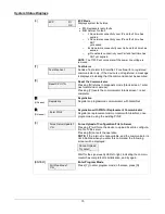
Once the installation is complete, press the [Shift] and the up arrow 

[

]


key on the 7720P.  The registration message is sent and the unit waits 

for the acknowledgment. 


Registration 
SUCCESS 

If this is a new installation and the city, central station, and customer 

numbers have been correctly entered, the communicator is registered 

and this message is displayed.  The communicator is now in full ser-

vice and available for alarm reporting to the central station. 


Summary of Contents for HWF2A-COM

Page 1: ... C CO OM M H HW WF F2 2A A C CO OM M C Co om mm me er rc ci ia al l F Fi ir re e C Co om mm mu un ni ic ca at to or r I In ns st ta al ll la at ti io on n a an nd d S Se et tu up p G Gu ui id de e 800 24452 9 18 Rev B ...

Page 2: ...g an existing communicator 8 Register by Phone 9 STEP 5 Configure the Fire Panel 9 STEP 6 Test the System 9 Dialer Capture Module Information 10 LED Display Information 10 Programmer Keyboard Commands 11 Identification Displays 11 Cellular Status Displays appear only if the communication path includes cell 12 LTE Displays 13 System Status Displays 15 Running Network Diagnostics 16 Possible Errors ...

Page 3: ...erify communications with the central station is successful by sending several events Also get confirmation that these events were received Operation The HWF2 COM replaces the fire panel s POTS communications path When an event occurs the fire panel goes off hook to dial the central station The HWF2 COM detects the off hook condition and provides the fire panel with a dial tone When the fire panel...

Page 4: ...mitter product procedures HWF2 COM Initial Power Up Upon initial power up the communicator LEDs blink in repeated sequence from top to bot tom indicating network initialization Green REG Yellow TX RX Red FAULT This sequence may take up to 15 minutes Do not reset power during this time When initialization is complete the Signal Quality display LEDs will light and the yellow and red LEDs may blink p...

Page 5: ...into the back plate holes 4 Connect the LED Display board to its connector then slide the board into the mounting rails Yellow LED and Buzz er are on top 5 Carefully remove the packaging material that surrounds the PowerBoost1 6 Mount the PowerBoost1 on the three unused standoffs Use the two metal screws and lock washers to fasten the left side of the circuit board Ensure the lock washers are loca...

Page 6: ...is fully seated All wiring terminals and connectors are tight All wiring has been completed and secured with cable ties 13 Install the battery not supplied Plug the power transformer in and attach the battery cable Wiring for Grounds Power and RF ...

Page 7: ...the key to accept the displayed default value xxx or enter the new value and press the key for the next prompt Use the Space key to scroll through a list of options 1 Connect the 7720P You can use the Shift A key to check the software revision 2 7720P PROGRAMMER Press 3 Start Prog Mode Y N Press Shift then Y then 4 Program Device Y N Press Shift then Y then 5 Com Path Choice IP Cell Press Space to...

Page 8: ...ce then press Follow the prompts 18 Exit Prog Mode Y N Press Shift then Y then press DONE NOTE If an error in programming occurs set the factory defaults see next topic and reprogram To exit the programming mode press N in response to the Review prompt Then press Y to the Exit Prog Mode prompt Upon exiting the root file is updated to log the changes made A message is displayed telling the user tha...

Page 9: ...registration sequence by clicking the Tamper Switch three times You can monitor the registration process by viewing the Status Display The Message yellow LED and the Status green LED will blink slowly in unison while registration is in progress Once the registration has been completed successfully the communicator enters normal operating mode the Status green LED goes out and the Message yellow LE...

Page 10: ... Registration BAD 2nd ID Need PIN This prompt is displayed if this is a repair replacement or an error was made in programming the Secondary account information of the com municator for an existing account This prompt appears for 2 seconds See the Replacing an existing communicator section below for further displays Registration BAD Pri 2nd Need PIN This prompt is displayed if this is a repair rep...

Page 11: ...e Supervision or Telco Fault on the panel is enabled Then choose a setting that is no higher than 90 seconds or as close to that as the panel allows 2 Ensure no more than 1 pause character usually a comma is programmed into the dialing string usually 2 seconds NOTE this is necessary since the Dialer Capture Module waits only 3 seconds after the phone number is dialed Having more than 3 seconds of ...

Page 12: ...mmunicator radio is not registered Old Alarm Time has been exceeded Message has not been delivered within the fixed 10 minute window Buzzer Upon loss of AC power this will beep once every 10 sec onds LOW BATTERY Yellow ON when battery is low 11 5VDC Yellow not used AC LOSS Yellow ON when no AC is present 90VAC AC ON Green ON when AC is present NOTE If a wire pulled out of the LED Board Connector r...

Page 13: ...indicates the MAC CRC number This number is found on the box and inside the communicator Press the Space key to go to the next field Press the backspace BS key to go to the IMEI display if the communication path includes cell NOTE The SCID and IMEI are displayed only if the communication path includes cell SCID xxxxx xxxxx xxxxx xxxxx SCID Display Displays the identification number assigned to the...

Page 14: ... Passed Performs a self test of the AES encryption algorithm Press the Space key to go to the next field Press the backspace BS key to go to the previous field DHCP OK DHCP Dynamic Host Configuration Protocol indicates server is performing satisfactorily Press the Space key to go to the Physical Link display Cellular Status Displays appear only if the communication path includes cell E Operating w...

Page 15: ...ent Reference Signal Received Quality MIN Minimum Receive Signal Quality MAX Maximum Receive Signal Quality Press the space key to get to the next screen Press the backspace key to go to the previous field Cntry Netw TAC xxx xxx xxxxx Location Display for LTE Cntry Country Code Netw Network Code TAC Tracking area code Press the space key to get to the next screen Press the backspace key to go to t...

Page 16: ...tw Network Code LAC Local area code Press the space key to get to the next screen Press the backspace key to go to the previous field Cell Chan PSC xxxxxx xxxx xxx Cell Display for 3G Cell Global Cell ID Chan Control Channel in use PSC Primary Sync Code Press the space key to go to the next screen Press the backspace key to go to the previous field Second Site RSSI Available 3G Status Display Scre...

Page 17: ...agnostic mode blank screen enter next command or escape Pressing Y resets the communicator blank screen reset complete UP arrow Registering Registration Registers a programmed communicator with AlarmNet DN arrow Enter PIN Registration with PIN for Replacement Communicator Registers a replacement communicator with AlarmNet once programmed using the existing PIN 0 Force Server Update Y N Force Uploa...

Page 18: ... is indicated here See below for possible errors that may occur at this stage of testing Redir 1 Service OK The service at AlarmNet Control on Redir 1 is functioning See below for possible errors that may occur at this stage of testing Testing Redir 2 The first step of the test traces the connection to Redir 2 at AlarmNet Control Redir 2 Service OK The service at AlarmNet Control on Redir 2 is fun...

Page 19: ...ile tracing the connection to Redir x the trace fails before ever reach ing the local gateway router Testing Redir x FAIL at Gtwy While tracing the connection to Redir x the trace fails after reaching the local gateway router Testing Redir x FAIL at Pvt IP While tracing the connection to Redir x the trace fails after reaching the private IP Testing Redir x FAIL on IP Addr While tracing the connect...

Page 20: ... BATT yellow Missing or low battery TROUBLE yellow One or more trouble conditions exist such as overload output supervision ground fault or charger failure NOTES If AC power is lost and the battery voltage falls below 10v the PowerBoost1 output voltage will be turned off The output power is turned back on when AC power is restored You must use the DIP switch settings shown below ...

Page 21: ...19 Communicator Information ...

Page 22: ... Failure We do not send a restoral R358 C0803 we send a failure message every day after the radio attempts to test and fails E358 C0803 N A Application Code Update E903 C08xx R903 C08xx success Application Code Update Failure E904 C08xx Module Firmware Update E365 C08xx R365 C08xx success Module Firmware Update Failure E366 C08xx Trouble Reporting The HWF2 COM does not support low missing battery ...

Page 23: ...ommunications path Telco 2 is cut Dialer Capture Module buffer is full Hang up Panel will retry giving the buffer a chance to empty HWF2 COM Specifications ITEM SPECIFICATION Cabinet Dimensions Width 12 3 4 inches Height 14 7 8 inches Depth 3 inches Transformer N8167 or N8167 1 Primary 120VAC 60Hz Secondary 18VAC 50VA Battery 12V 7Ah sealed lead acid type not supplied Use a Honeywell 712BNP Yuasa ...

Page 24: ...22 NOTES ...

Page 25: ...23 NOTES ...

Page 26: ...24 NOTES ...

Page 27: ...ires When replacing a wire or component ensure the wire is routed in the same manner as the original factory wire NOTE Wire colors may vary NOTES All circuits are power limited except the backup battery which is non power limited Non power limited wiring must be separated from the power limited wiring by at least 1 4 inch If desired use a Honeywell 955WH Tamper Switch with the 28 2 bracket ...

Page 28: ...the receiver control into a different outlet so that it and the radio or television receiver are on different branch circuits Consult the dealer or an experienced radio TV technician for help FCC STATEMENT This device complies with Part 15 of the FCC Rules Operation is subject to the following two conditions 1 This device may not cause harmful interference and 2 This device must accept any interfe...

Reviews: