SYSTEM INSTALLATION MANUAL
KTR 2280A
Page 2-2
15 May 2017
© Honeywell International Inc. Do not copy without express permission of Honeywell.
The installation must be in accordance with standards established by the customer's installing agency and
existing conditions as to unit location and type of installation; however, the following must be considered before
installing the system in order to assure a more satisfactory performance from the equipment.
NOTE: The TSO identifies the minimum performance standards, tests, and other conditions applicable for
issuance of design and production approval of the article. The TSO applicant is responsible for
documenting all limitations and conditions suitable for installation of the article. An applicant
requesting approval for installation of the article within a specific type or class of product is responsible
for determining environmental and functional compatibility.
Care must be exercised to avoid mounting components near equipment operating with high pulse current or
high rf power outputs such as radar and satellite communications equipment. In general, the equipment must
be installed in a location convenient for operation, inspection, and maintenance, and in an area consistent with
the TSO environmental limits. Determine the mounting location for system components following the guidelines
below
2.3.2.1 Mounting Tray Location(s)
The KTR 2280A MMDR mounting tray can be installed in any convenient location.
2.3.2.2 Antenna(s)
The antenna(s) must be well removed from other antenna projections, the engine(s), and propeller(s). It must
also be well removed from landing gear doors, access doors, or other openings which will break the ground
plane for the antenna(s). On metal skinned aircraft, the antenna(s) must be bonded to the surface of the aircraft
in a fore to aft location that provides the flattest ground plane. On composite aircraft, the antenna(s) must be
located at the center of a conductive ground plane, contoured to the shape of the aircraft, having dimensions of
at least 2 feet by 2 feet. The antenna penetration must be designed such that the structural integrity of the
fuselage is not compromised. The antenna(s) need to be within 5 degrees of the centerline.
Where practical, plan the antenna location(s) to keep cable lengths as short as possible and avoid sharp bends
in the cable to minimize the VSWR. Avoid running other cables or wires near the antenna cable(s).
On pressurized aircraft, the antenna(s) must be sealed using an approved sealant, such as RTV No. 3145 (PN
016-01082-0000) or equivalent, around the connector and mounting hardware.
The antenna edge and mounting hardware recesses must be sealed from the outside for moisture protection
using RTV or equivalent.
Mount the antenna(s) in as clean as environment as possible, away from exhaust gases and oils. The
antenna(s) must be kept clean. If left dirty (oil covered), the antenna performance can be affected.
2.3.3 KTR 2280A Mechanical Installation
The mounting tray for the MMDR must be mounted using the dimensions specified in the outline and mounting
drawing, Figure 2-21 (KTR 2280A Installation Drawing). Install the unit as follows:
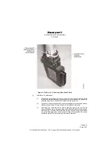
(1) Slide the MMDR into the tray until the locking rod engages the nut on the back of the
rack.


